Cable tray assemblies

a technology of conductive cables and assemblies, applied in the direction of rod connections, couplings, machine supports, etc., can solve the problem of reducing the probability that a cable will be ensnared on a sharp exposed edg

Active Publication Date: 2009-06-16
SINKOFF HOWARD
View PDF30 Cites 47 Cited by
  • Summary
  • Abstract
  • Description
  • Claims
  • Application Information

AI Technical Summary

Benefits of technology

[0011]The present invention provides an array of cable trays that conform to the National Electric Code's rigorous requirements of continuous grounding while providing aesthetically pleasing and highly functional cable tray components that are interconnected by a novel attachment system.
[0012]Among the several objects of the invention may be noted the provision of an improved junction for joinder of cable trays; the provision of such a junction which can be used as supplied and without requiring extras or taking special steps to enable pulling cable around from one tray run to another in a manner avoiding damage to the cable (e.g. in the case of data transmission cable, avoiding distortion of the quality of the data transmissability thereof); the provision of such a junction for joinder of cable trays in different configurations, particularly, but not by way of limitation, in L-formation, T-formation, or cruciform formation; and the provision of such a junction which is relatively economical to manufacture and convenient and economical to install.
[0014]In one aspect of the invention, cable tray sections are provided having an “L” shape, others are provided in a “T” shape, and others are provided in a cruciform shape. Further shapes may be provided, such as elbows (L-shaped sections) which do not form 90° angles, T-shaped sections a portion or all of which do not form a 90° angle, and cruciform shapes which have angles other than 90° included. Rounding the interior angles of these cable tray sections reduces the amount of bending of the cables that pass around each angle, and thus reduces distortion of the quality of data transmissions. Further, rounding the interior angles reduces the likelihood that a cable will become ensnared on a sharp exposed edge.
[0017]In yet a still further aspect of the invention, rollers are provided with some or all of the cable tray sections for facilitating the drawing of cables thereover.

Problems solved by technology

Further, rounding the interior angles reduces the likelihood that a cable will become ensnared on a sharp exposed edge.

Method used


Image

  • Cable tray assemblies
  • Cable tray assemblies
  • Cable tray assemblies

Examples


Embodiment Construction

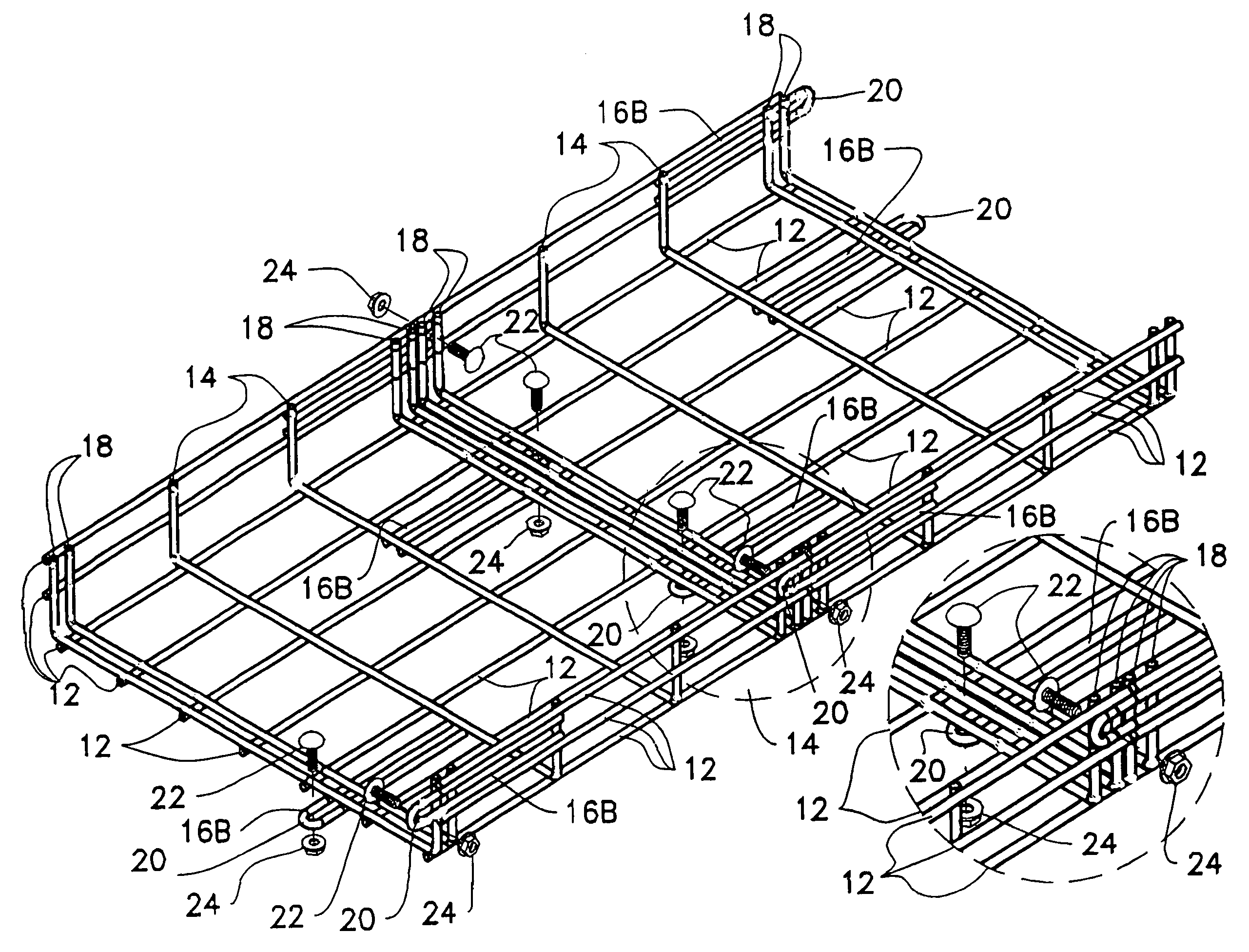
[0055]As shown in FIG. 1, prior art cable trays are comprised of longitudinal wires 12, also known as “warp” wires, that run longitudinally, and transverse wires 14, also called “weft” wires, running perpendicularly to the warp wires and welded or otherwise permanently connected thereto to form a U-shaped basket or tray. The sections 1 are of any suitable length, and adjacent sections (not shown) are connected to each other on-site by cutting off wire segments, if necessary, and clamping the cable tray sections together. As stated previously, requiring workers in the field to cut the cable tray sections and clamp them together is not only cumbersome, time-consuming and costly, but potentially dangerous.

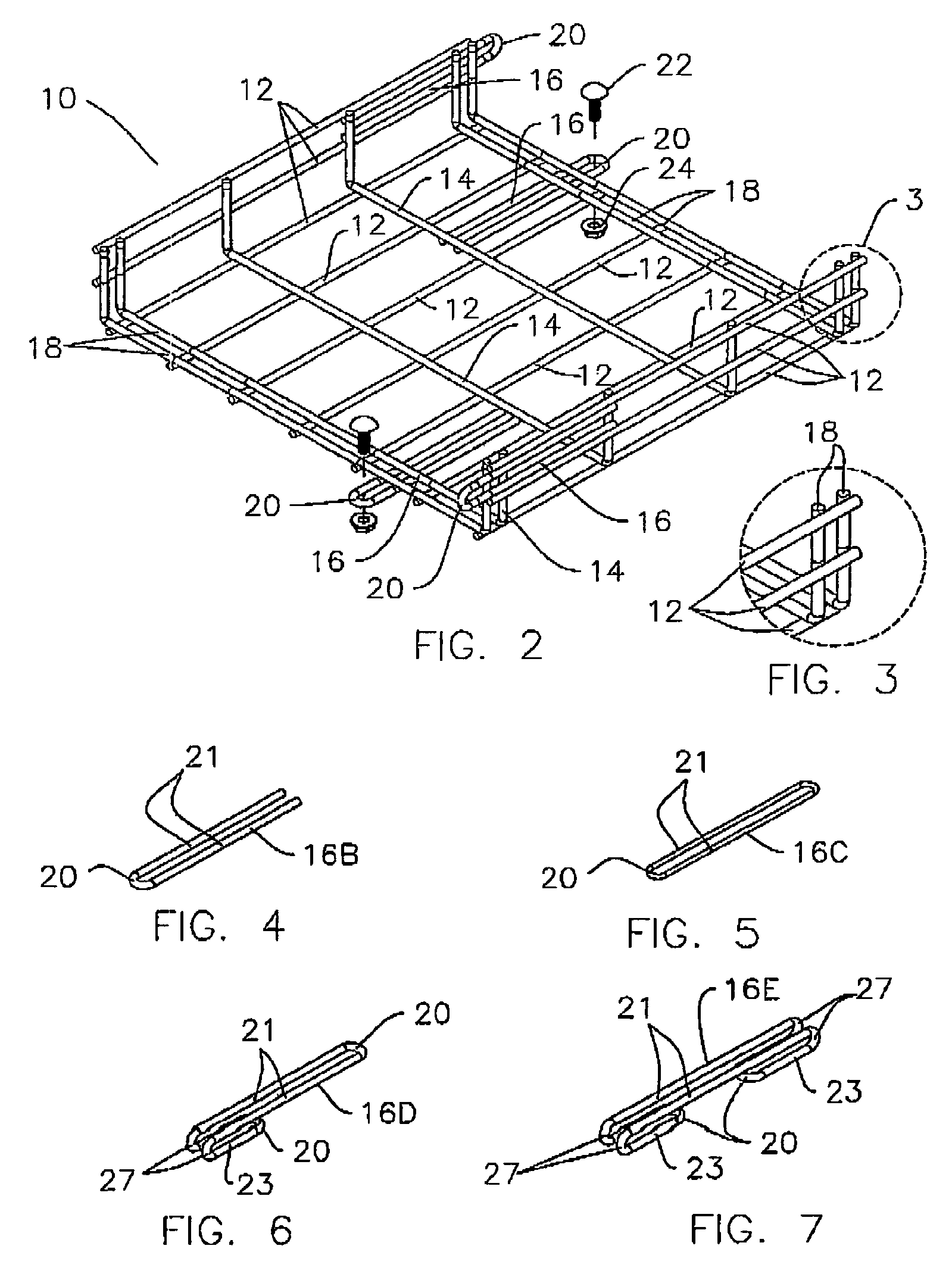
[0056]As shown in FIGS. 2 and 13-14, the cable tray connecting system of the instant invention may utilize an otherwise standard cable tray 10, which can be comprised of longitudinal wires 12 interconnected with transverse wires 14. One improvement of the instant invention lies in the...


PUM


Abstract

A cable tray is provided for supporting conductive cable and a system is provided to connect cable trays to create secure cable pathways to safely organize and support conductive cable. The system includes improved junctions for joinder of cable trays in any desired pre-formed shape that eliminates exposed sharp edges and allows for fast, easy installation. Various shaped connectors between adjacent cable trays provide secure, easy-to-install connections and maintain electrical conductivity between adjacent trays. A system for surface treating the cable trays renders the trays electrically non-conductive at desired portions of each cable tray, while leaving exposed certain portions of each tray. Mask blanks that fit the connectors and selected portions of the cable tray are used to expose electrically conductive portions of the cable trays during the treatment of the cable trays. Rollers are provided to facilitate drawing cables over the tray.

Description

BACKGROUND OF THE INVENTION[0001]1. Field of the Invention[0002]This invention relates generally to apparatus and systems for supporting conductive cable, and, more particularly, relates to components of, and systems which utilize, cable trays to securely and safely organize and support conductive cable.[0003]2. Background Art[0004]Cable tray assemblies are well known for use as a support system for carrying conductive cable, wires, tubing, piping, or other conduits over various distances in buildings and other commercial structures. The cable tray assembly provides a support for running the wires throughout various locations in the facility. Cable trays are typically suspended from the ceiling or walls in order to provide a non-intrusive path for the cable that allows for full use of the work spaces below. Due to the amount of cable and conduit running through modern facilities, cable trays are also available which support cables at multiple elevations.[0005]It has become common pr...

Claims


Application Information

Patent Timeline
Patent Type & Authority Patents(United States)
IPC IPC(8): F16L3/22F16L3/26H02G3/04H02G3/06
CPCH02G3/0443H02G3/0608Y10T403/34
Inventor SINKOFF, HOWARD
Owner SINKOFF HOWARD
Why Eureka
Try Eureka