Freezing point temperature measuring method and temperature calibrating method in differential scanning calorimetry

a technology of differential scanning calorimetry and temperature measurement method, which is applied in the direction of material heat development, instruments, and investigating phase/state change, etc., can solve the problems of difficult to realize a stable freezing procedure, limited amount of sample which can be installed in the apparatus, and inability to directly insert the thermocouple into the sampl

Inactive Publication Date: 2009-06-16
HITACHI HIGH TECH SCI CORP
View PDF4 Cites 10 Cited by
  • Summary
  • Abstract
  • Description
  • Claims
  • Application Information

AI Technical Summary

Benefits of technology

[0020]A method of analyzing the DSC curve of the invention is based on a discovery that as shown by a DSC curve (1) of freezing indium of FIG. 4, in a heat generating peak in freezing a sample, with regard to a region showing a constant rightward rising inclination, there is provided a range showing a state in which the sample is at the constant temperature at the freezing temperature. By using data of the range, even in a sample showing supercooling, the freezing point can accurately be calculated. For example, there is discovered and adopted a method of analyzing the DSC curve, the output temperature curve, in which an output temperature of an intersection of an extrapolated tangential line from the DSC curve, the output temperature curve, and a base line of a range constituting a liquid state including a supercooled state or an extension thereof is read and the freezing point of the sample is constituted by the temperature of the intersection.

Problems solved by technology

Further, although according to a method other than the differential scanning calorimetry, there is a method of measuring a temperature by directly inserting a thermocouple to a sample, in view of a structure of a differential scanning calorimetric apparatus, the thermocouple cannot directly be inserted into the sample and also an amount of the sample which can be installed in the apparatus is limited.
Therefore, a systematic error by a heat flow is produced in a temperature measured value, and it is difficult to realize a stable freezing procedure over a long period of time since the sample amount is small.

Method used


Image

  • Freezing point temperature measuring method and temperature calibrating method in differential scanning calorimetry
  • Freezing point temperature measuring method and temperature calibrating method in differential scanning calorimetry
  • Freezing point temperature measuring method and temperature calibrating method in differential scanning calorimetry

Examples


Embodiment Construction

[0032]An embodiment of the invention will be explained in reference to the drawings.

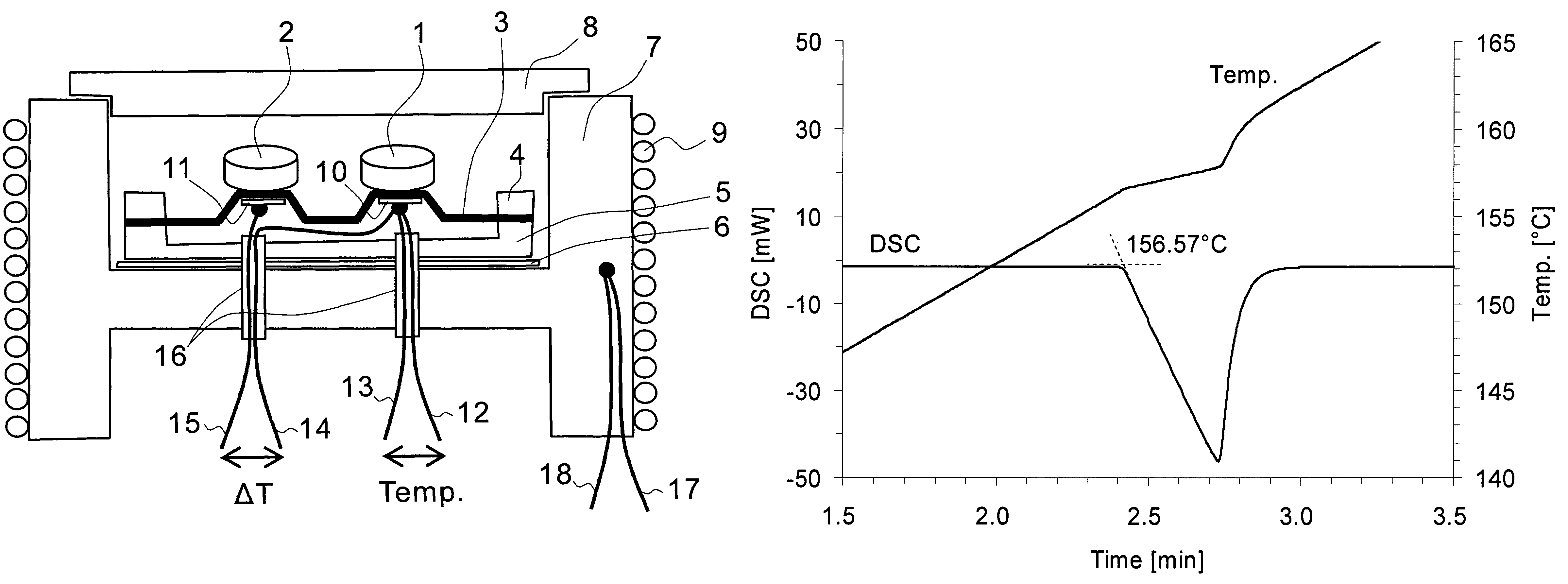
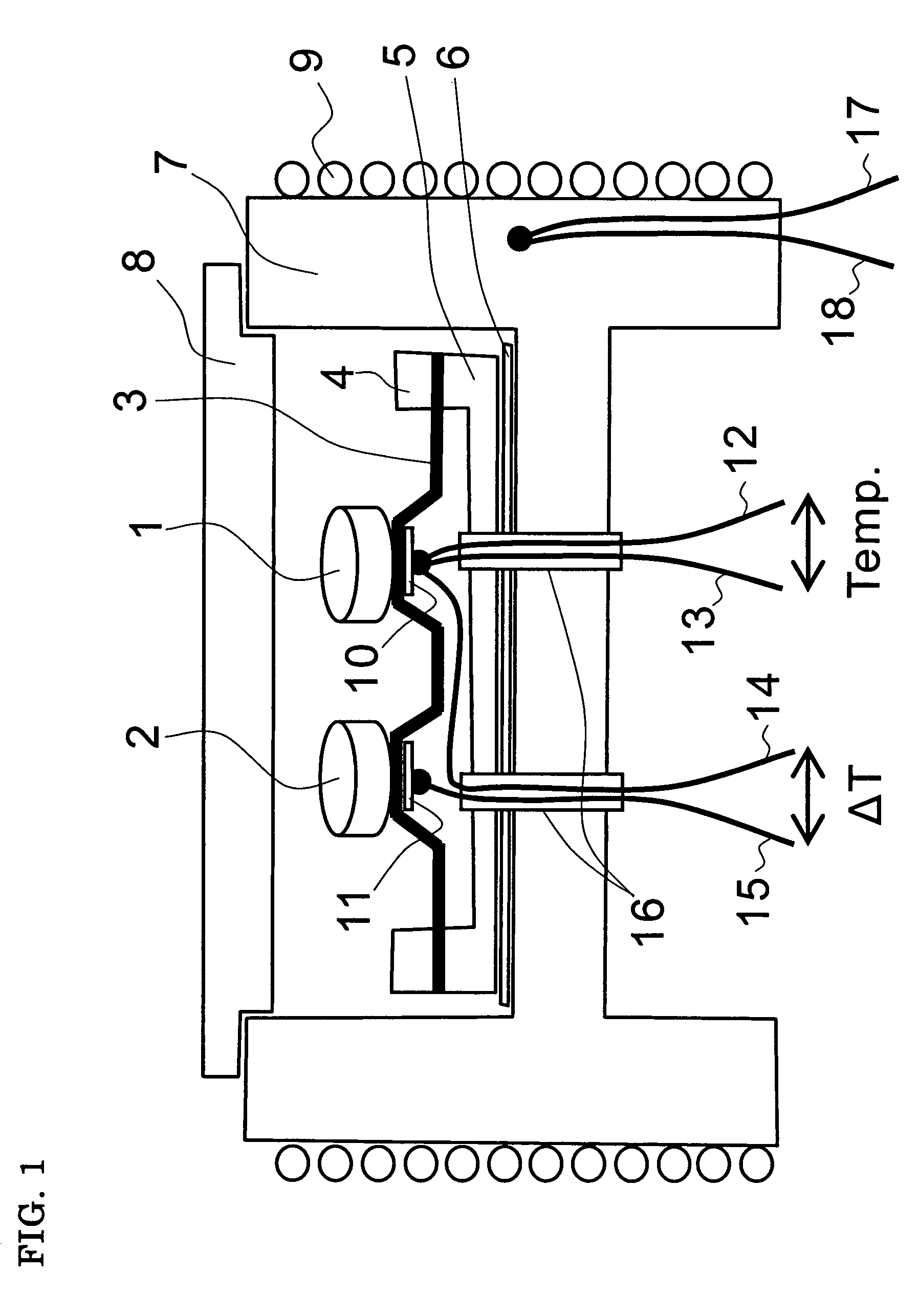
[0033]FIG. 1 shows an example of a differential scanning calorimetric apparatus used in the invention, and a sectional view of a sensor portion. The apparatus of FIG. 1 is an example disclosed in Japanese Patent No. 3137605 (See FIG. 1). The apparatus is a representative example and the invention is generally applicable to a differential scanning calorimetric apparatus in which a temperature sensor is not directly inserted into a sample.

[0034]A sample vessel 1 and a reference substance vessel 2 are made of aluminum, a size thereof is about 5 mm in a diameter, a sample showing supercooling is put into the sample vessel 1, a reference substance of aluminum or alumina powder or the like is put into the reference substance vessel 2, normally, a lid made of aluminum is covered thereon to be crimped. Amounts of the sample and the reference substance are normally several mg through several 10 mg. The respec...


PUM

PropertyMeasurementUnit
diameteraaaaaaaaaa
diameteraaaaaaaaaa
diameteraaaaaaaaaa

Abstract

It is discovered that a range of showing a state in which a sample is at a constant temperature at a freezing temperature by a latent heat can be specified from a result of a differential scanning calorimetry in a cooling procedure and a method of acquiring the freezing point of the sample from data in the range is shown. For example, an output temperature of an intersection constituted by a tangential line extrapolated from a DSC curve, an output temperature curve, and a base line or an extension of a range brought into a liquid state including a supercooled state is read, and a method of analyzing the DSC curve, the output temperature curve constituting the freezing point of the sample by a temperature of the intersection is discovered and adopted.

Description

[0001]This application claims priority under 35 U.S.C. §119 to Japanese Patent Application No. JP2006-035265 filed Feb. 13, 2006, the entire content of which is hereby incorporated by reference.BACKGROUND OF THE INVENTION[0002]The present invention relates to a method of analyzing a DSC curve for accurately acquiring a freezing point of a sample showing supercooling by differential scanning calorimetry, and a method of carrying out temperature calibration in cooling of a differential scanning calorimetric apparatus by using a sample evaluated with a freezing point.[0003]In differential scanning calorimetry of a background art, a freezing point of a sample showing supercooling is not acquired, or a crystallizing temperate is read as shown in FIG. 2 of Nonpatent reference 1 (see below) and Nonpatent Reference 2 (see below).[0004]Nonpatent Reference 3 (see below) shows a method of measuring an evaluated freezing point of a sample by a crucible method as a temperature calibrating method...

Claims


Application Information

Patent Timeline
Patent Type & Authority Patents(United States)
IPC IPC(8): G01N25/04G01K15/00G01K19/00G01K3/00
CPCG01N25/20
Inventor NAKAMURA, TOSHIHIKO
Owner HITACHI HIGH TECH SCI CORP
Why Eureka
Try Eureka