
Compact and rugged imaging Raman spectrograph

a raman spectrograph, compact technology, applied in the field of optical spectroscopy systems, can solve the problems of lack of robustness, compactness, cost-effective construction required for routine deployment in the field of on-line industrial process automation and control, prior-art designs do not incorporate design methodologies, etc., to maximize grating efficiency and enhance optical throughput and efficiency

Inactive Publication Date: 2009-06-16
NGUYEN QUANG VIET
View PDF18 Cites 19 Cited by
  • Summary
  • Abstract
  • Description
  • Claims
  • Application Information

AI Technical Summary

Benefits of technology

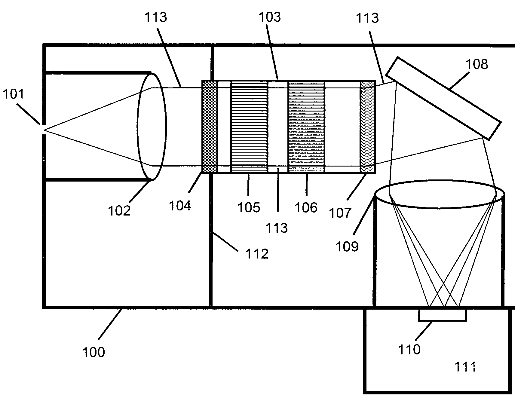
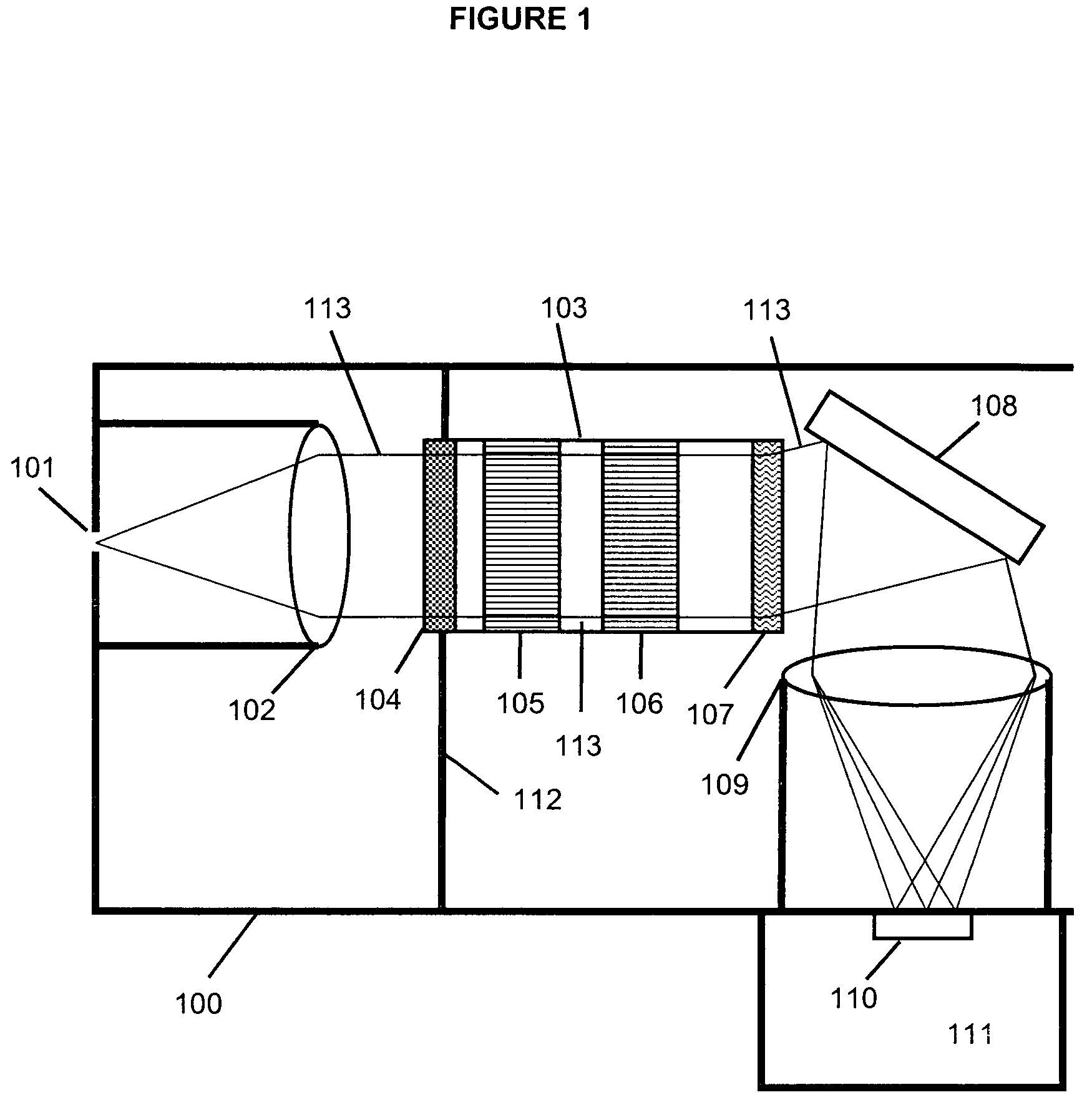
[0004]The present invention seeks to provide a compact and robust imaging spectrograph that is suitable for field-deployable Raman spectroscopy for real-time industrial and chemical process measurement and control. According to one embodiment of the invention, an imaging Raman spectrograph utilizes commercially available aberration-corrected compound optical lenses with focal lengths ranging from about 10 mm to 100 mm, with f numbers ranging from f / 1.0 to f / 2.8, an elastically scattered light, or Rayleigh-line rejection filter assembly comprising a multi-layer dielectric interference filter or a holographic notch filter, a transmission grating, an optional beam folding mirror, and an optical housing and frame to locate and align the previously mentioned optical components in a robust and compact mechanical assembly. The spectrograph further has the advantage of using a relay lens assembly consisting of a first lens or lens assembly (a lens assembly refers to a cohesive group of aberration corrected lens elements mounted in such a way as to act as a single lens with an effective focal length), which relays the image of the input slit to the second lens or lens assembly, which images the spectrally dispersed image of the slit onto the detector image plane. This relay lens assembly requires only two lenses or lens assemblies, rather than the four lens or lens assemblies typically required by the prior art in order to accommodate a spectral pre-filter relay lens assembly that precedes the dispersive relay lens or lens assembly. The preferred embodiment of the invention is modified from a traditional understanding of a relay lens assembly insofar as a dispersive element is provided between the relay lens elements Specifically, the dispersive elements is a transmission diffraction grating. In addition, the spectrograph includes a first lens or lens assembly, a spectral filter assembly that rejects the elastically scattered light from the excitation source, a transmission grating, and a second lens or lens assembly. The use of this relay lens assembly also permits the user to selectively change the first and second lens or lens assemblies, and specifically to change the focal lengths of these lenses in order to tailor the magnification or the spectral band width of the spectrograph. Furthermore, the relay lens or lens assembly may include a mechanical or electromechanical shutter to block the transmission of light through the relay lens or lens assembly.
[0007]Additionally, the spectrograph system described in the present invention can be constructed from a one-piece ‘unibody’ type design to minimize both parts and to provide a more secure and reliable system of mounting the optical components to minimize the effects of misalignments due to mechanical movement between various optical components. The unibody construction can be effected by various means such as computer numerical controlled (CNC) machining whereby a solid block of metal such as aluminum is formed by removing large amounts of internal material corresponding to the cavities inside the housing.
[0010]According to another embodiment, the spectrograph can utilize a transmission volume phase holographic (VPH) grating to enhance the optical throughput and efficiency. Such gratings have transmission efficiencies as high as 90% in the visible wavelength range. The VPH grating will typically be mounted in an angled fashion to maximize the grating efficiency by satisfying the Bragg angle condition of the grating.

Problems solved by technology

Most of these systems have been developed for use in a laboratory environment, and as a result, can be quite fragile and sensitive to misalignment, they also lack the robustness, compactness, and cost-effective construction required for routine deployment in the field such as on-line industrial process automation and control.
However, these prior-art designs do not incorporate design methodologies shown in the present design which incorporates features that will enable a simple, rugged, cost-effective and easy-to-use design, with a combined spectral filter assembly for the purposes of rejecting the elastic light scattering without the use of one or more additional lens assemblies.

Method used


Image

  • Compact and rugged imaging Raman spectrograph
  • Compact and rugged imaging Raman spectrograph
  • Compact and rugged imaging Raman spectrograph

Examples


Embodiment Construction

[0020]An embodiment of the compact and rugged imaging Raman spectrograph of the present invention is schematically shown in FIG. 1. The spectrograph 100 has an input optical slit 101 that admits light into the spectrograph, and at the same time serves to spatially limit the input slit image dimensions for the purposes of determining the spectral resolution and spatial extent of the slit image. The slit will have dimensions ranging from 5 μm to 200 μm in the spectral dimension, and heights ranging from 1 mm to 12 mm in spatial dimension. The light from the slit is then collimated preferably by a commercially available multi-element anti-reflection (AR) coated compound lens 102 (or lens assembly). The lens 102 has typical focal lengths, depending on the resolution and spectral range requirements that range from 10 mm to 100 mm, and with f / #'s (focal ratio number) ranging from f / 1.0 to f / 2.8. The invention permits the user to change this lens in order to change the focal length which p...


PUM


Abstract

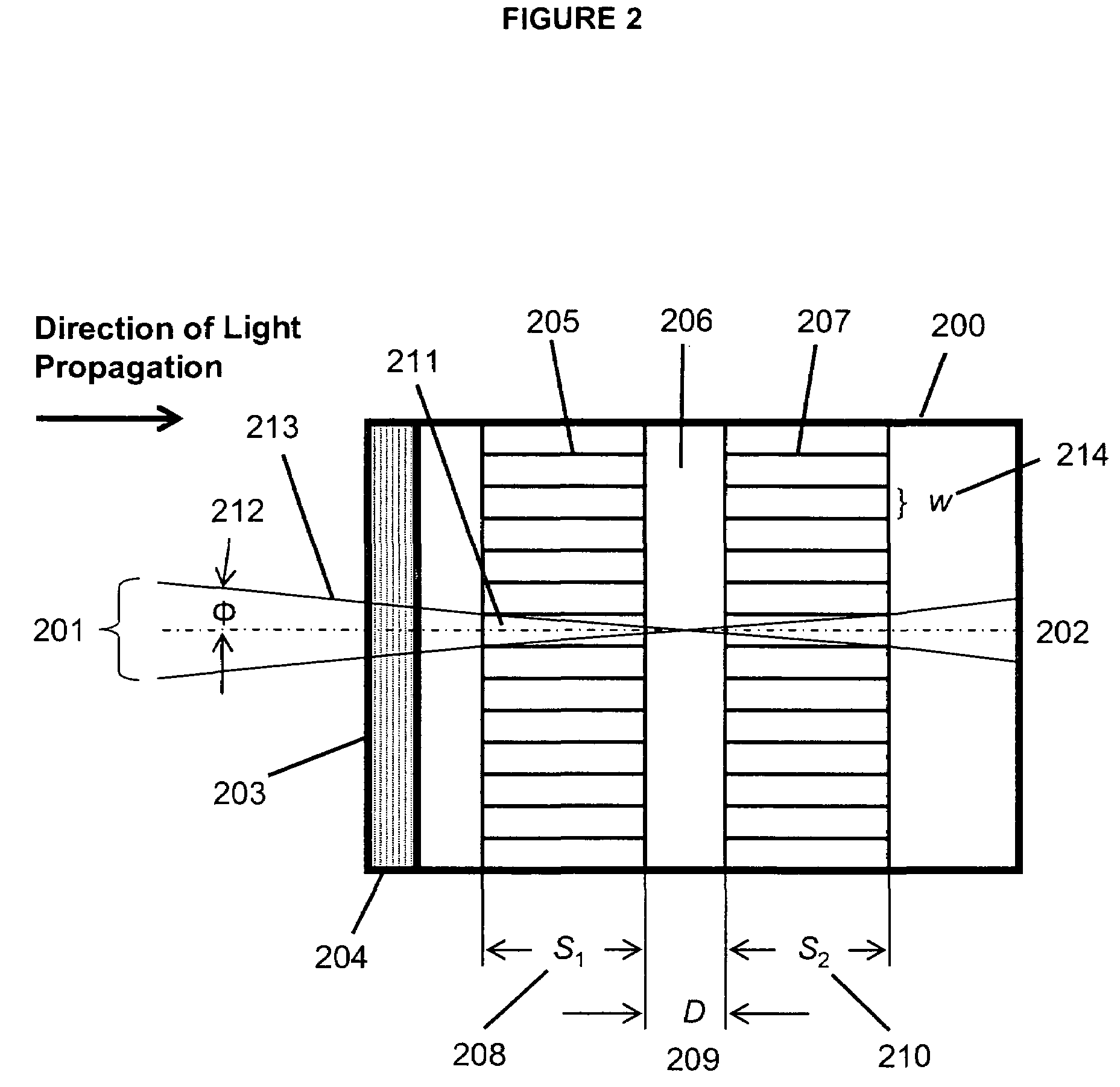
A compact and robust imaging Raman spectrograph has a collimating input lens assembly, a spectral filter assembly, a transmission diffraction grating, a focusing lens assembly, and a light detector. The spectral filter assembly is located between the two lenses and comprises a notch or long-pass filter optical interference filter, a plurality of optical channel plates for limiting the optical acceptance angle of the light passing the optical interference filter, and a transmission diffraction grating, all mounted in a single assembly. The spectral filter assembly permits a very high degree of elastically scattered light rejection and excellent stray-light reduction and management, while permitting a high level of optical throughput to maximize the signal of the weakly scattered Raman signal.

Description

FIELD OF INVENTION[0001]The present invention relates to optical spectroscopy systems for measuring dispersed light wavelengths for the purposes of producing an optical spectrogram. In particular, the present invention is directed to systems and processes for performing Raman spectroscopy in the so called imaging mode whereby the spectrogram is three dimensional: wavelength, spatial extent, and signal intensity. In specific embodiments, the invention allows for the use of Raman spectroscopy to analyze the chemical compositions of substances using the Raman-effect through an attached fiber optic Raman probe with a linearly disposed array of optical fibers, or via free-space lens-coupled configurations.BACKGROUND OF THE INVENTION[0002]The applications and principles of Raman spectroscopy are well-known and thus will not be described here in detail. Briefly, Raman spectroscopy is an in-elastic light scattering technique that that uses the Raman-effect. In a typical Raman spectroscopy s...

Claims


Application Information

Patent Timeline
Patent Type & Authority Patents(United States)
IPC IPC(8): G01J3/28
CPCG01J3/02G01J3/0208G01J3/0227G01J3/0262G01J3/26G01J3/44B33Y80/00
Inventor NGUYEN, QUANG-VIET
Owner NGUYEN QUANG VIET
Learn More