
Method for tuning a GPS antenna matching network

a technology of global positioning system and antenna matching, applied in the field of wireless communication, can solve problems such as significant degradation of antenna efficiency, and achieve the effect of reducing antenna efficiency and reducing antenna efficiency

Inactive Publication Date: 2009-06-16
KYOCERA CORP
View PDF180 Cites 10 Cited by
  • Summary
  • Abstract
  • Description
  • Claims
  • Application Information

AI Technical Summary

Benefits of technology

[0005]Changes in the return loss (matching) of an efficient GPS antenna, due to hand loading or other detuning effects, can translate into a very significant degradation of antenna efficiency. Although losses in the antenna's efficiency due to user hand-absorption are not correctable, the detuning of the GPS internal antenna can be restored if the antenna's matching network can be dynamically adjusted to match the impedance of the antenna with the user's hand over the handset. Preliminary measurements have indicated that approximately a 1.5 dB improvement in the ratio of unmodulated signal power (C) to the power spectral density of the background noise (N), carrier-to-noise ratio (C / N) can be restored by properly adjusting the antenna's matching network.
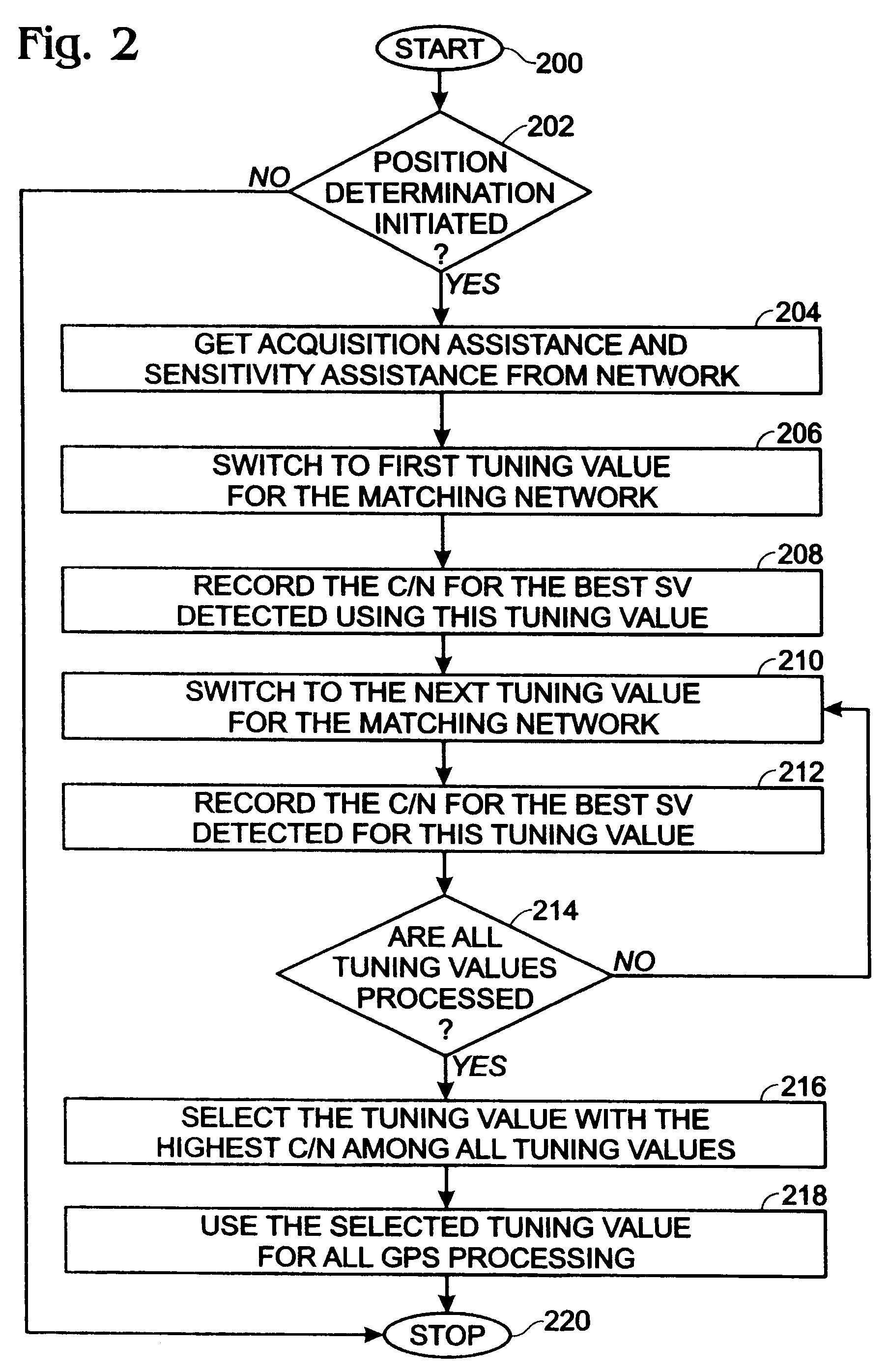
[0006]The use of a tunable matching network corrects for the detuning, or changes in the proximate environment, to improve the overall antenna efficiency. Tuning the matching network has the effect of “correcting” the impedance mismatch with the GPS antenna and, hence, lowering the return loss at 1575 MHz. Tuning the matching network also has an effect of tuning the frequency of the matching network. The invention described herein provides a suitable control algorithm, for use with a tunable matching circuit, for maximizing the efficiency of a GPS antenna. This algorithm provides feedback to the matching circuit, based on GPS system parameters, such as number of received satellites, C / N, or the like. Different algorithms may be used depending on search time available.
[0007]In another aspect, the wireless device may operate in a hybrid mode, using satellite vehicle (SV) and base station pilots, in which case a reduced number of SVs may be required. Another strategy is to perform searches in both directions (higher and lower) from a default tuning value, measuring the C / N, and picking a direction based upon the highest measured C / N. Then, tuning and measuring C / N can be continued in the same direction. If the difference in the C / N value improvement between one iteration and the next becomes smaller, or falls below a certain threshold, the tuning can be stopped.

Problems solved by technology

Changes in the return loss (matching) of an efficient GPS antenna, due to hand loading or other detuning effects, can translate into a very significant degradation of antenna efficiency.

Method used


Image

  • Method for tuning a GPS antenna matching network
  • Method for tuning a GPS antenna matching network
  • Method for tuning a GPS antenna matching network

Examples


Embodiment Construction

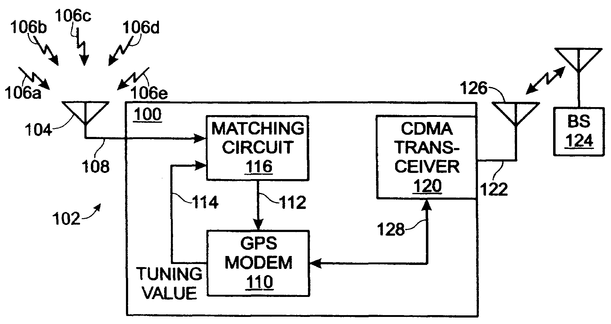
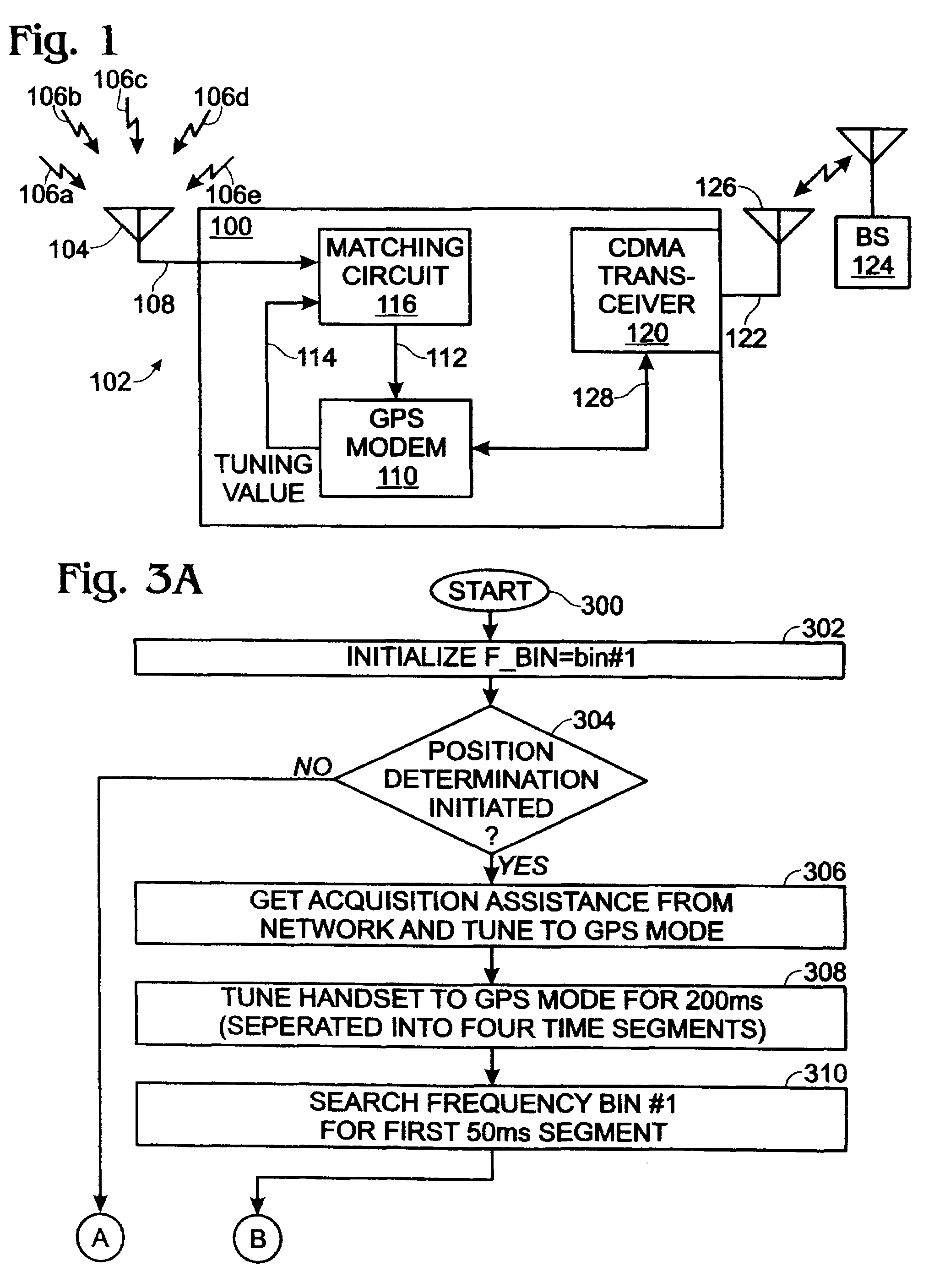
[0018]FIG. 1 is a schematic block diagram of an exemplary system for tuning a Global Positioning System (GPS) antenna matching circuit portable wireless communications device 100 according to one embodiment of the invention. The system 102 comprises an antenna 104 for receiving Satellite Vehicle (SV) signals radiated through an air or space medium, represented by reference designators 106a through 106e. The number of visible SVs (SVs whose signals can be received) is dependent upon geographic features near the wireless device 100, device altitude, and weather conditions. Generally however, an absolute minimum of three SVs are required to determine a stationary position. Four SVs are minimally required to determine the position of a moving device 100. Often, a wireless device 100 is able to receive signals from eight SVs simultaneously in an outdoor environment. The antenna 104 has an interface 108 (i.e., a hardwire such as a coaxial line connector) for supplying conducted SV signals...


PUM


Abstract

A system and method is provided for tuning a Global Positioning System (GPS) antenna matching circuit in a portable wireless communications device. The method includes accepting a first matching circuit tuning value, measuring satellite vehicle (SV) carrier-to-noise ratio (C / N) associated with the first tuning value and a first search time interval, measuring the SV C / N associated with a next tuning value, and selecting the tuning value associated with the highest SV C / N to tune the matching circuit. In one aspect, the method further includes comparing the SV C / N to a first minimum threshold. If the first tuning value SV C / N exceeds the first minimum threshold, then the method measures the SV C / N associated with the next tuning value. Otherwise, a default tuning value can be selected to tune the matching circuit.

Description

FIELD OF THE INVENTION[0001]This invention generally relates to wireless communications and, more particularly, to a system and method for tuning a Global Positioning System (GPS) antenna matching circuit.BACKGROUND OF THE INVENTION[0002]Many handheld communication devices now have the capability of receiving and processing GPS signals. The GPS antennas of these devices are usually embedded internally, and separated from the other communication systems. Those antennas are narrowband in nature, since they only have to cover a very narrow portion (about 10 Megahertz (MHz) of the spectrum around 1575 MHz, while minimizing interaction with any other communication system antennas within the same device. Due to the narrow bandwidth of these antennas, they are particularly sensitive to changes in the proximate environment, such as loading associated with a user's hand. Small changes in the proximate environment can produce a significant detuning of the antenna and, consequently, greatly de...

Claims


Application Information

Patent Timeline
Patent Type & Authority Patents(United States)
IPC IPC(8): H04M1/00
CPCH04B1/18H04B1/3805
Inventor FABREGA-SANCHEZ, JORGECHANG, HENRYVEERARAGHAVAN, SRIVATSANKITABI, AMMAR
Owner KYOCERA CORP
Learn More