Surface mount crystal oscillator

a surface mount crystal and oscillator technology, applied in the field of crystal oscillators, can solve the problems of insufficient electric connections between crystal blanks and the limitations of crystal oscillators to reduce size, and achieve the effects of reducing size, high functional added value, and increasing the area availabl

Inactive Publication Date: 2009-06-23
NIHON DEMPA KOGYO CO LTD
View PDF7 Cites 9 Cited by
  • Summary
  • Abstract
  • Description
  • Claims
  • Application Information

AI Technical Summary

Benefits of technology

[0014]It is an object of the present invention to provide a surface mount crystal oscillator which is capable of reducing the outer planar dimensions thereof while ensuring an area available for accommodating an IC chip in a package, improving the airtightness or sealability in a space in which a crystal blank and the IC chip are contained, and ensuring electric connections between the IC chip and crystal blank.
[0017]In the configuration as described above, since the crystal blank is secured to and held on the inner bottom surface of the cover, the package body need not be provided with a step on the inner wall of the recess, thus making it possible to increase an area available for accommodating the IC chip in the package body. The present invention is particularly suitable for a reduction in size of a surface mount crystal oscillator which has highly functional added values such as a surface mount temperature compensated crystal oscillator. Also, since the first and second annular metal films are connected with the eutectic alloy, and the first and second crystal connection terminals are also bonded with the eutectic alloy, the airtightness of sealability is improved between the package body and insulating cover, and the reliability of the electric connection between the IC chip and crystal blank is also improved.

Problems solved by technology

Particularly, the temperature compensated crystal oscillator requires larger IC chip 2 due to a temperature compensation mechanism integrated in IC chip 2, so that the resulting crystal oscillator has limitations to a reduction in size.
However, the crystal oscillator described in JP-A-2000-134037 experiences difficulties in maintaining the airtightness or sealablility in a space in which the crystal blank is sealed, and is prone to suffer from insufficient electric connections between the crystal blank and IC chip, because the insulating cover is secured to the package body with the anisotropic conductive adhesive.

Method used


Image

  • Surface mount crystal oscillator
  • Surface mount crystal oscillator
  • Surface mount crystal oscillator

Examples


Embodiment Construction

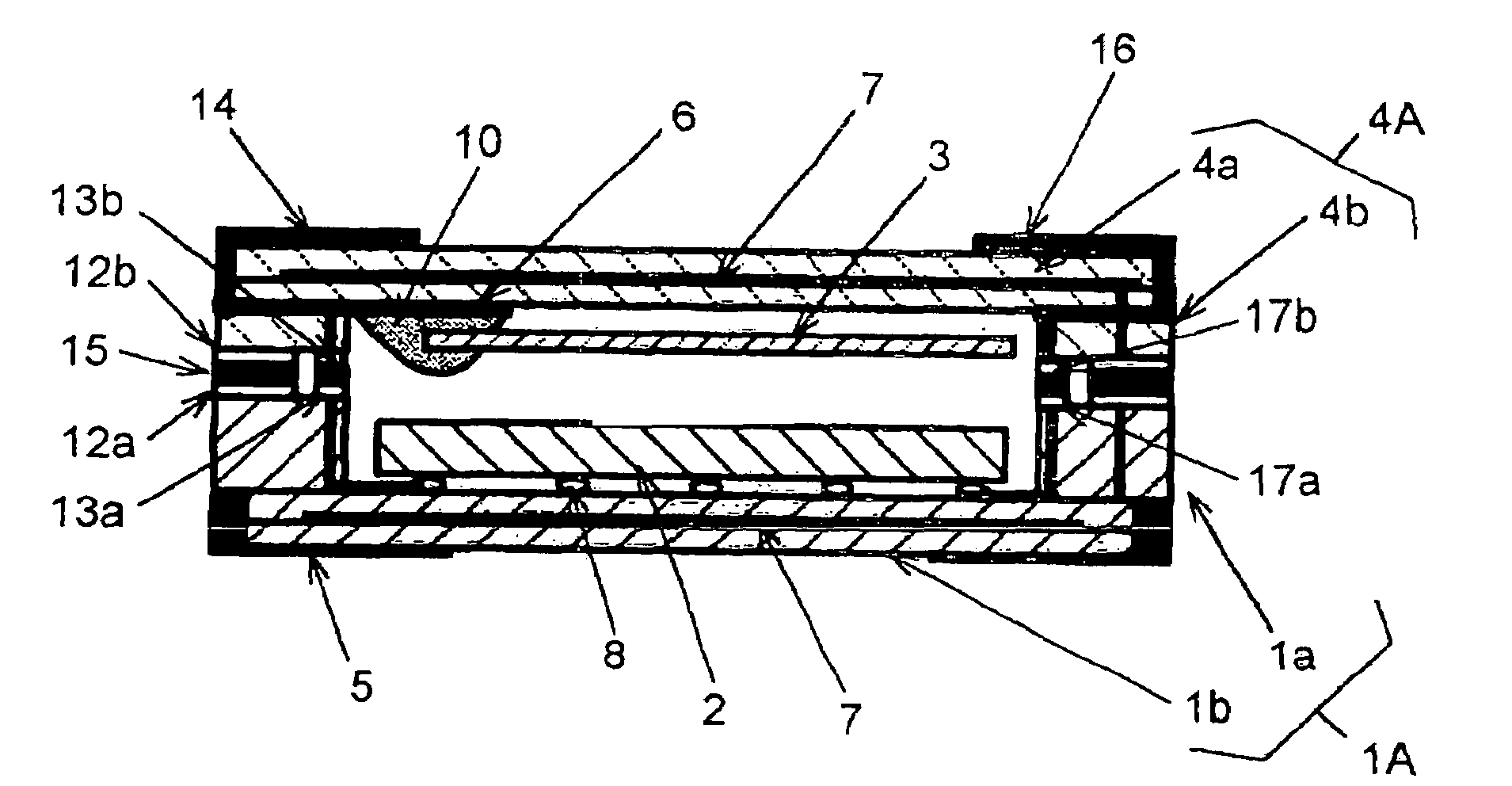
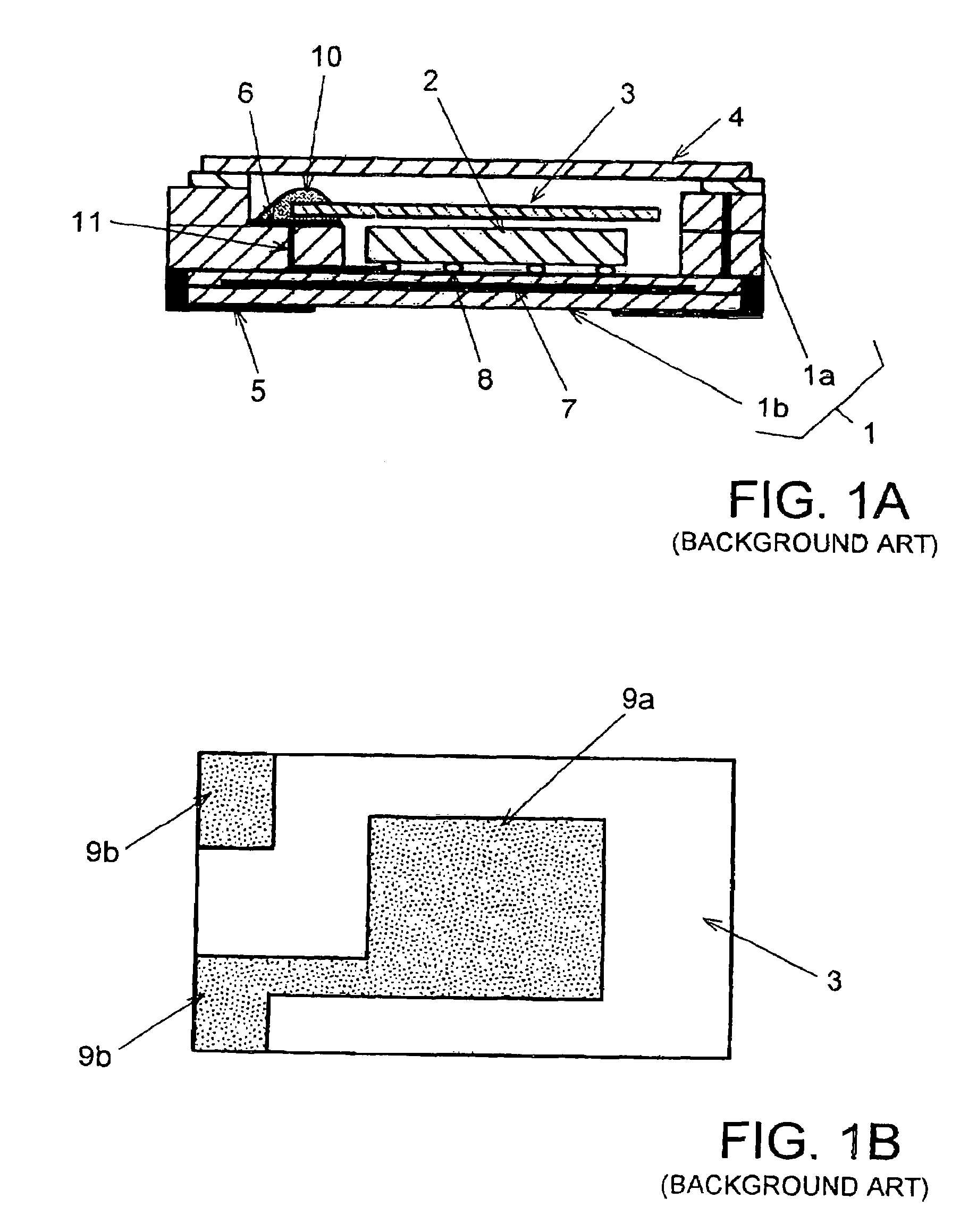
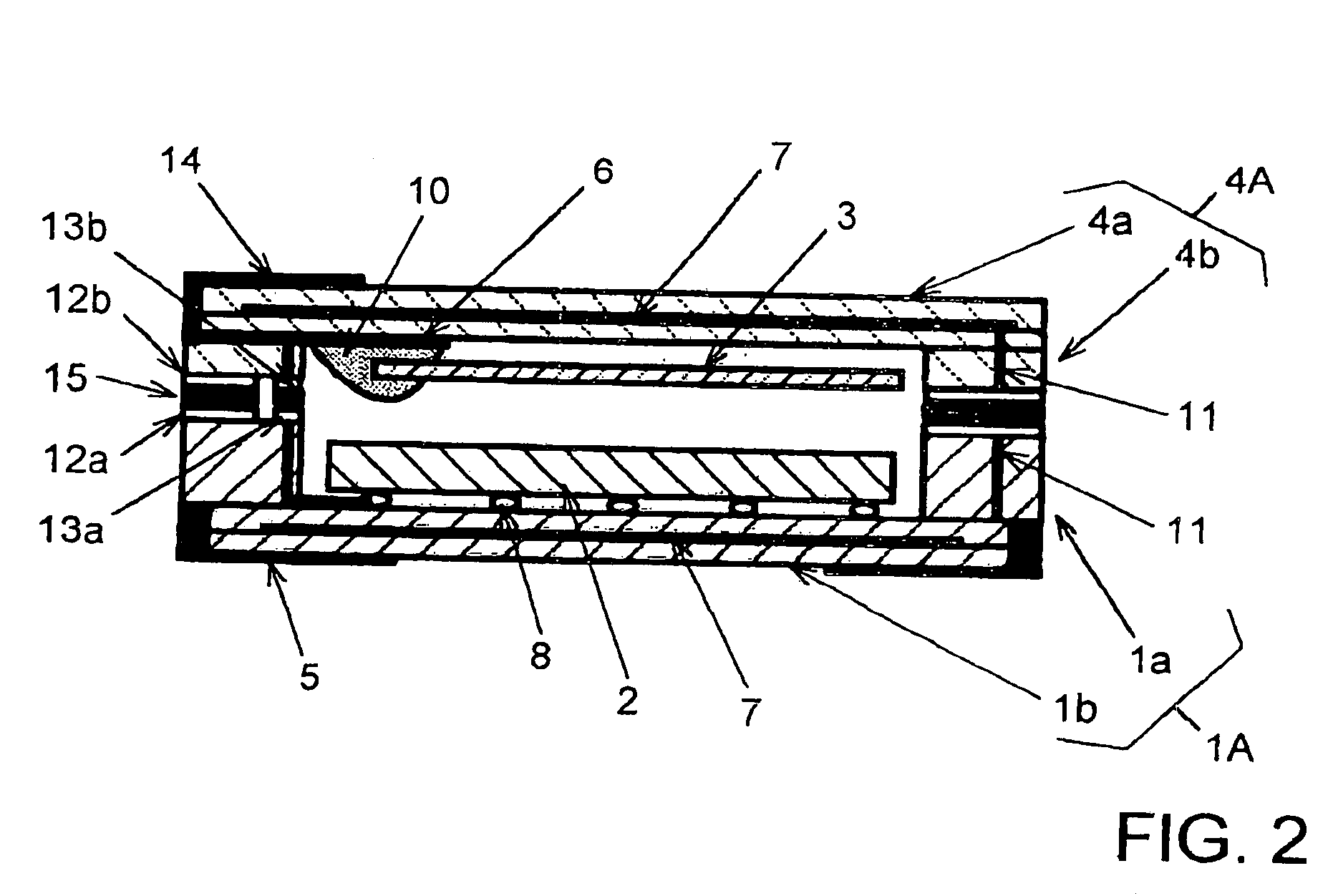
[0025]In FIG. 2 which illustrates a surface mount crystal oscillator according to one embodiment of the present invention, the same components as those in FIG. 1A are designated the same reference numerals, and repeated descriptions will be omitted.

[0026]The surface mount crystal oscillator illustrated in FIG. 2 comprises package body 1 of a surface mount type having a recess, and insulating cover 4A formed in a concave shape. Insulating cover 4A is bonded to package body 1A for integration such that the recess of package body 1A opposes the recess of insulating cover 4, to hermetically seal IC chip 2 and quartz crystal blank 3 in a space defined by package body 1A and insulating cover 4A. Package body 1A is formed of laminated ceramics which include flat and substantially rectangular bottom wall layer 1b, and frame wall layer 1a having a substantially rectangular opening. The opening formed through frame wall layer 1a defines a recess. Mounting terminals 5 are disposed at four corn...


PUM


Abstract

A surface mount crystal oscillator comprises a package body having a first recess, a cover having a second recess, a crystal blank secured to an inner bottom surface of the second recess, and an IC chip secured to a bottom surface of the first recess. The IC chip has an oscillation circuit using the crystal oscillator integrated therein, and has IC terminals on one main surface for connection to the outside. A first and a second annular metal film are disposed to surround open end surfaces of the first recess and second recess, respectively. By bonding the first and second annular metal films with an eutectic alloy, the crystal blank and IC chip are hermetically sealed in a space defined by the integrated first and second recesses.

Description

BACKGROUND OF THE INVENTION[0001]1. Field of the Invention[0002]The present invention relates to a crystal oscillator which comprises a crystal blank and an IC (integrated circuit) chip that has integrated therein an oscillation circuit using the crystal blank, both of which are contained in a surface mount package, and more particularly, to a surface mount crystal oscillator which ensures an area for accommodating an IC chip in a package.[0003]2. Description of the Related Arts[0004]Surface mount crystal oscillators, which have a quartz crystal blank and an IC chip that has integrated therein an oscillation circuit using the crystal blank, both of which are contained in a surface mount package, are built in a variety of portable electronic devices in particular as reference sources for frequency and time because of their small sizes and light weights. Particularly, a temperature compensated crystal oscillators are widely employed in mobile telephones and the like because such tempe...

Claims


Application Information

Patent Timeline
Patent Type & Authority Patents(United States)
IPC IPC(8): H03B1/00H01L41/053H03B5/32
CPCH03B5/32
Inventor HARIMA, HIDENORI
Owner NIHON DEMPA KOGYO CO LTD
Why Eureka
Try Eureka