Common rail fuel injection system designed to avoid error in determining common rail fuel pressure

a common rail and fuel pressure sensor technology, applied in the direction of machines/engines, anti-theft devices, electric control, etc., can solve the problem of unsatisfactory change in the drive voltage applied to the sensor element of the fuel pressure sensor

Inactive Publication Date: 2009-06-30
DENSO CORP
View PDF14 Cites 12 Cited by
  • Summary
  • Abstract
  • Description
  • Claims
  • Application Information

AI Technical Summary

Benefits of technology

[0010]It is another object of the invention to provide a common rail fuel injection system designed to avoid an error of fuel pressure feedback control arising from, for example, remodeling of an electronic control unit and a fuel pressure sensor in order to increase an output of an engine, thereby minimizing physical damage to the common rail to ensure a desired service life thereof.
[0012]If a resistor is added to the harness or a disconnection of the hardness with the electronic control unit or the fuel pressure sensor, it will result in an undesirable change in the drive voltage applied to the sensor element of the fuel pressure sensor. In such an event, the voltage error monitor determines that the drive voltage, as sampled by the voltage sampling circuit, is in error to avoid an error in computing the pressure in the common rail. This permits the electronic control unit to avoid an excessive rise in the pressure in the common rail, thereby protecting the common rail from physical damage to ensure a desired service life of the common rail.
[0014]When it is determined by the voltage error monitor that the drive voltage, as sampled by the voltage sampling circuit, is in error, the electronic control unit may correct the target fuel pressure with which the pressure within the common rail is brought into agreement under feedback control to a value which is at least required to ensure an operation of the engine.
[0020]Even when the voltage supplied to the fuel pressure sensor undergoes a change due to, for example, addition of a resistor to a connection between the fuel pressure sensor and the electronic control unit in order to increase an output of the engine, the power supply circuit installed in the fuel pressure sensor serves to produce the constant power supply voltage, thus ensuring the stability in producing an output of the fuel pressure sensor. This avoids an error in determining the pressure in the common rail.

Problems solved by technology

If a resistor is added to the harness or a disconnection of the hardness with the electronic control unit or the fuel pressure sensor, it will result in an undesirable change in the drive voltage applied to the sensor element of the fuel pressure sensor.

Method used


Image

  • Common rail fuel injection system designed to avoid error in determining common rail fuel pressure
  • Common rail fuel injection system designed to avoid error in determining common rail fuel pressure
  • Common rail fuel injection system designed to avoid error in determining common rail fuel pressure

Examples


first embodiment

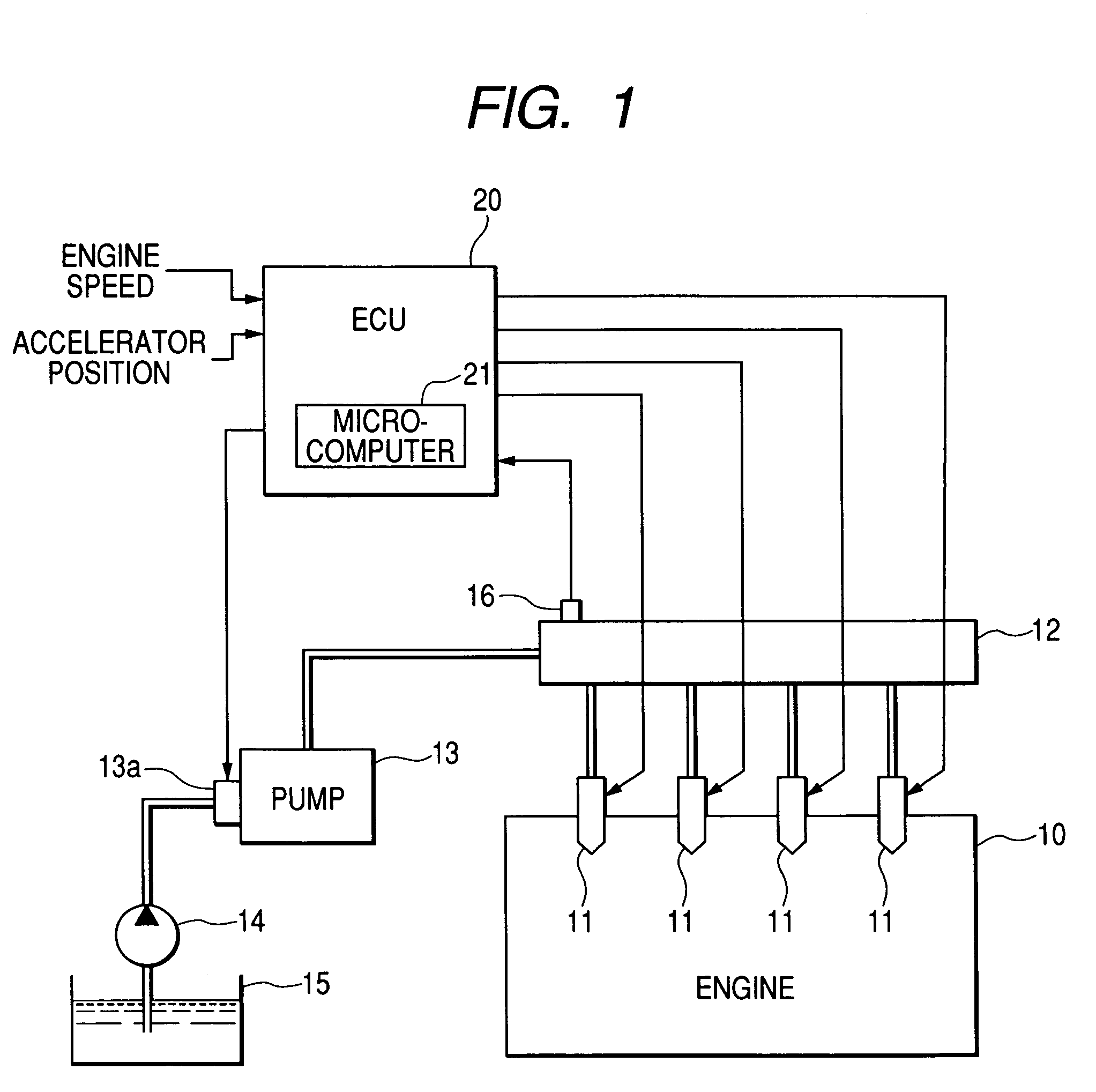
[0031]Referring to the drawings, wherein like reference numbers refer to like parts in several views, particularly to FIG. 1, there is shown a fuel injection system according to the invention which is designed as a common rail fuel injection system (also called an accumulator injection system) working to control injection of fuel into multi-cylinder diesel engines.

[0032]The fuel injection system includes solenoid-operated injectors 11 each for one of cylinders of the engine 10. The injectors 11 are hydraulically connected to a common rail 12 which serves as a fuel accumulator. A high-pressure pump 13 is connected to the common rail 12 and works to supply fuel to the common rail 12 and accumulate it at a pressure substantially equivalent to a required fuel injection pressure. A solenoid-operated suction control valve 13a is installed on the high-pressure pump 13. The high-pressure pump 13 sucks the fuel pumped by a feed pump (i.e., a low-pressure pump) 14 out of a fuel tank 15 throug...

second embodiment

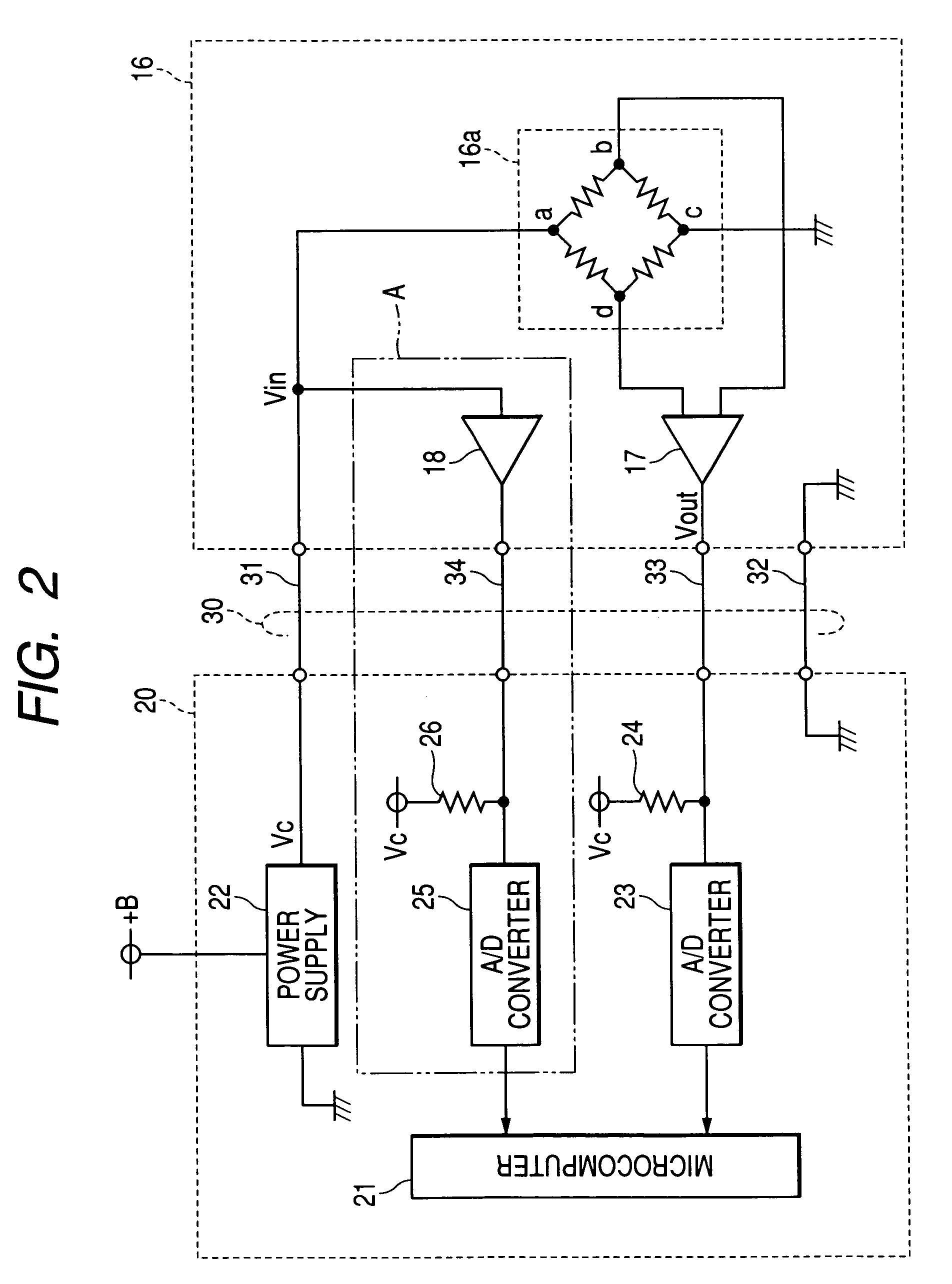
[0058]FIG. 6 illustrates internal structures of the ECU 20 and the fuel pressure sensor 16 according to the invention. The same reference numbers as employed in FIG. 2 refer to the same parts, and explanation thereof in detail will be omitted here.

[0059]The fuel pressure sensor 16 includes an arithmetic circuit 51 made by a microcomputer which works to determine whether the internal drive voltage Vin is in error or not.

[0060]The fuel pressure sensor 16 and the ECU 20 are coupled with each other through a harness 40. The harness 40 consists of three wires and connectors (not shown) joined to ends of the wires. The fuel pressure sensor 16 and the ECU 20 also have connectors mating with the connectors of the harness 40. The ECU 20 includes the power supply circuit 22 which supplies the electric power to the fuel pressure sensor 16 through the power supply line 41. The fuel pressure sensor 16 and the ECU 20 are kept at a common reference potential through the reference potential line 42...

third embodiment

[0066]FIG. 7 illustrates internal structures of the ECU 20 and the fuel pressure sensor 16 according to the invention. The same reference numbers as employed in FIG. 2 refer to the same parts, and explanation thereof in detail will be omitted here.

[0067]The fuel pressure sensor 16 and the ECU 20 are coupled with each other through a harness 60. The harness 60 consists of three wires and connectors (not shown) joined to ends of the wires. The fuel pressure sensor 16 and the ECU 20 also have connectors mating with the connectors of the harness 40.

[0068]The ECU 20 is equipped with a transistor 71 and a resistor 72. The transistor 71 is connected at a base thereof to the microcomputer 21, at an emitter thereof to the power supply circuit 22, and at a collector thereof to the fuel pressure sensor 16 through the resistor 72 and the power supply line 61. The microcomputer 21, the power supply circuit 22, the transistor 71, and the resistor 72 constitute a power supply unit. The microcomput...


PUM


Abstract

A common rail fuel injection system includes an electronic control unit and a fuel pressure sensor. The electronic control unit is equipped with a power supply circuit which supplies a power supply voltage to the fuel pressure sensor through a harness. The power supply voltage is used in the pressure fuel sensor as a drive voltage to drive a sensor element of the fuel pressure sensor. The electronic control unit monitors an output voltage of the fuel pressure sensor to determine the pressure of fuel in a common rail and also monitors the drive voltage applied to the fuel pressure sensor to determine whether the drive voltage is undesirably lower than the power supply voltage or not. If such a condition is encountered, the electronic control unit takes measures to avoid an excessive rise in pressure in the common rail to protect the common rail physically.

Description

CROSS REFERENCE TO RELATED DOCUMENT[0001]The present application claims the benefit of Japanese Patent Application No. 2005-243556 filed on Aug. 25, 2005, the disclosure of which is incorporated herein by reference.BACKGROUND OF THE INVENTION[0002]1. Technical Field of the Invention[0003]The present invention relates generally to a common rail fuel injection system equipped with a fuel pressure sensor working to measure the pressure of fuel within a common rail and an electronic control unit working to monitor an output of the fuel pressure sensor to determine the pressure within the common rail, and more particularly to such a system designed to avoid an error in determining the pressure within the common rail.[0004]2. Background Art[0005]Japanese Patent First Publication No. 2002-276500 discloses one example of typical common rail fuel injection systems which includes a common rail in which fuel is accumulated under a given high pressure and fuel injectors working to inject the fu...

Claims


Application Information

Patent Timeline
Patent Type & Authority Patents(United States)
IPC IPC(8): F02M69/54
CPCF02D41/222F02D41/3845F02D2041/223F02D2041/285F02D2250/31F02M2200/18
Inventor OSAKI, MASATOYO
Owner DENSO CORP
Why Eureka
Try Eureka