
Laser device triggered by a photonic fiber

Inactive Publication Date: 2009-07-07
EOLITE SYST
View PDF9 Cites 7 Cited by
  • Summary
  • Abstract
  • Description
  • Claims
  • Application Information

AI Technical Summary

Benefits of technology

[0050]The laser of the invention is a triggered pulse laser, with high gain and guided mode (with MPF fibre) which has a short pulse duration and uses a simple opto-electronics triggering means whereof the triggering time is not critical for the pulse duration and may be greater than the laser pulse duration.

Problems solved by technology

Such confinement imposes conventionally a great absorption length and a high limitation in the energy produced by triggering.
However it is very difficult to maintain losses greater than the gain during the pumping period.
The laser is then limited to rates of the order of 100 kHz and the triggering system is particularly costly.
Moreover the system is sensitive to the polarisation of the wave propagating in the resonator and its efficiency may be diminished by the de-polarisation during the propagation through the fibre.

Method used


Image

  • Laser device triggered by a photonic fiber
  • Laser device triggered by a photonic fiber
  • Laser device triggered by a photonic fiber

Examples


Embodiment Construction

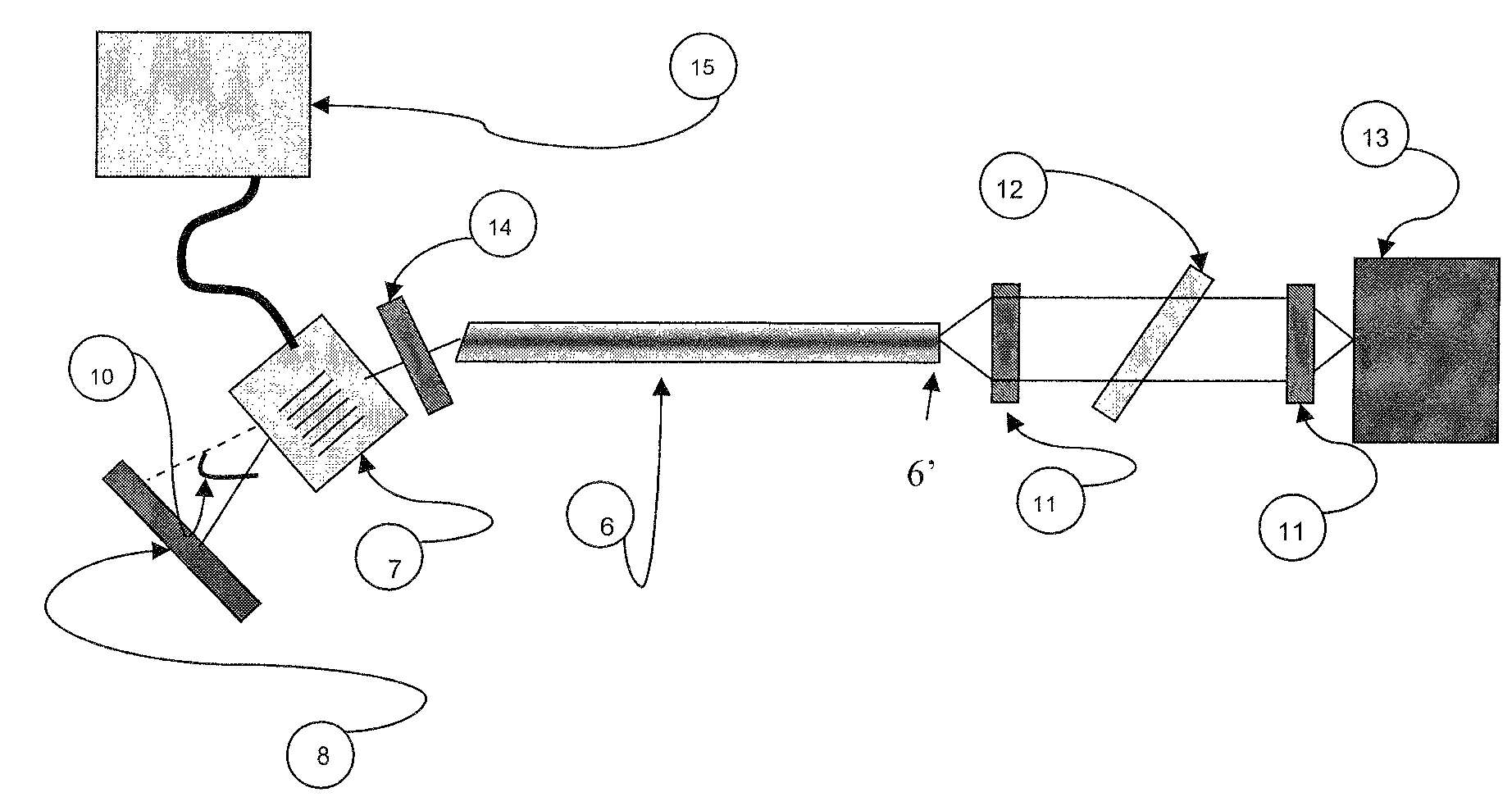
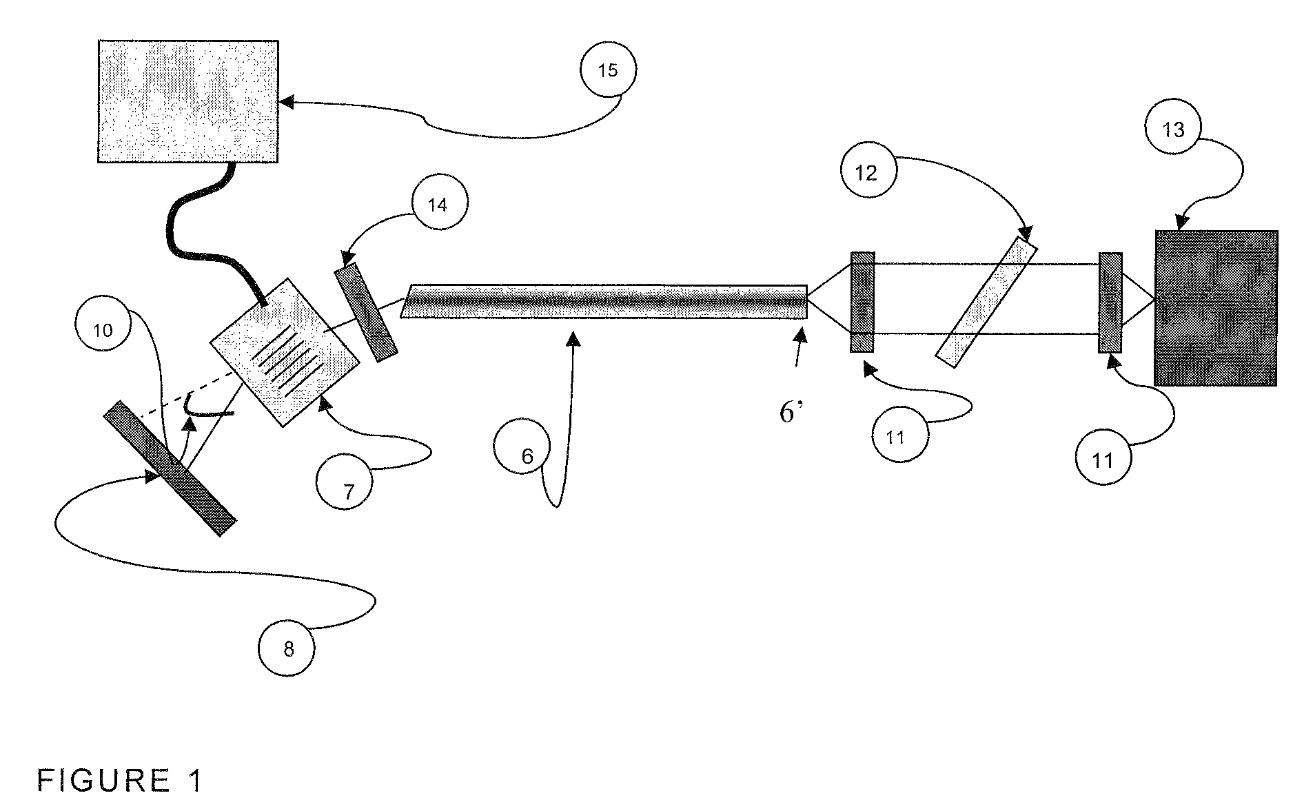
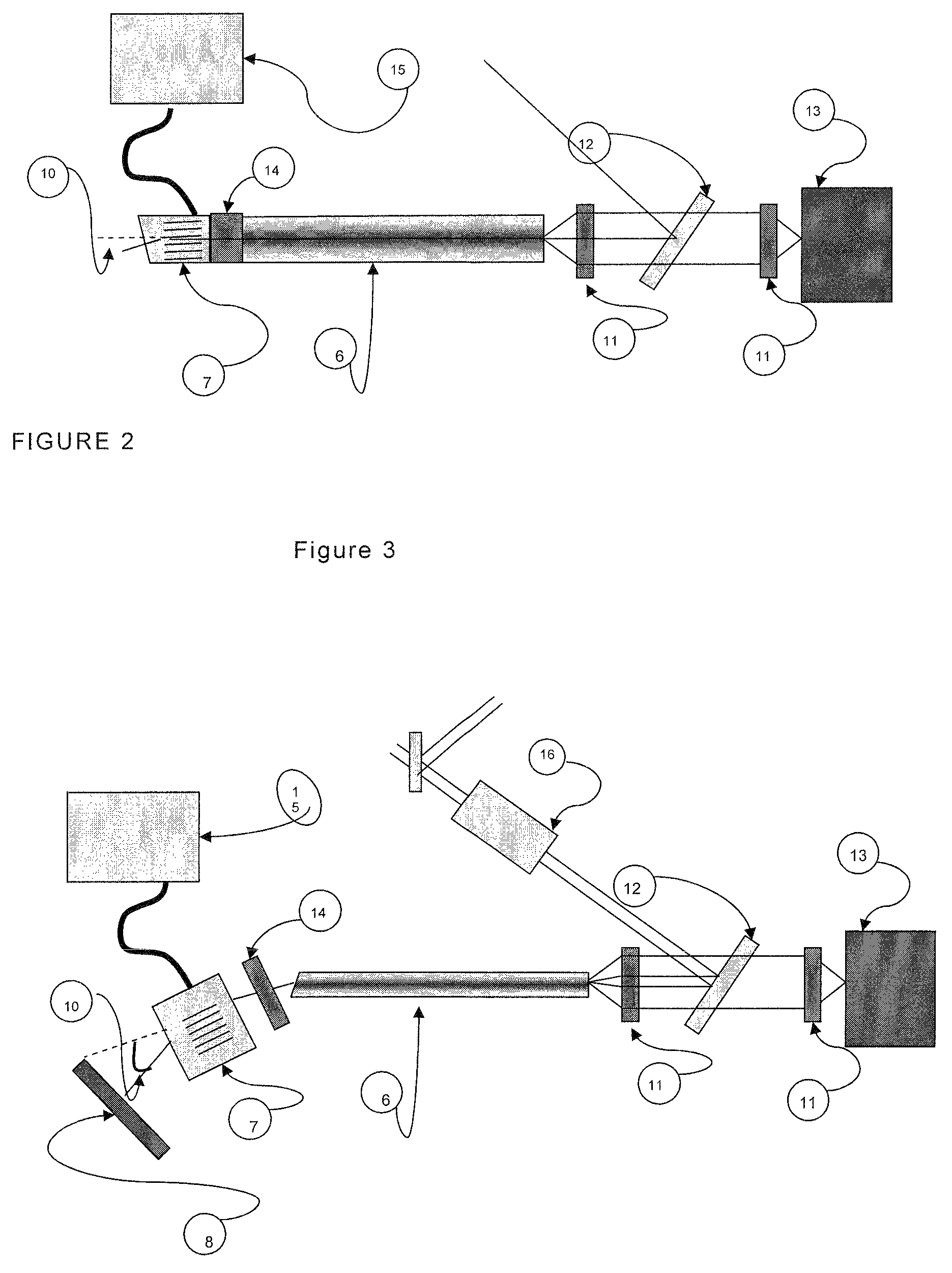
[0055]On FIG. 1, a laser resonator is formed between a reflecting mirror 8 at the laser transmission wavelength and a planar end 6′ of an MPF photonic fibre 6. The second end de the MPF fibre is cut or polished so as to form an angle typically 8° (between 1° and 60°) with the longitudinal axis of the fibre. The light beam emerging from the tilted end side fibre is collimated using a lens 14 on an acousto-optical modulator 7. This light beam is then incident on the acousto-optical modulator 7 which may produce at output at least two different angular paths for the beam. The modulator 7 is activated at the desired shooting rate by an electronic module 15, which controls a high frequency acoustic wave created in the modulator during the activation. The mirror 8 is positioned so that its normal forms an angle Θ10 corresponding to the angle between the incident beam on the modulator (and which corresponds to the output beam with a non-activated modulator) and the diffracted beam accordin...


PUM


Abstract

A device producing laser pulses of durations smaller than 30 ns, and including along its internal optical axis: a laser resonator of optical length smaller than 2 m including two reflecting ends and incorporating an MPF photonic fiber pumped continuously by at least one pump wave with laser diodes, the laser medium being a medium where the laser wave is guided and has a gain with very weak signal greater than 10 per passage, the resonator also incorporating an optical modulator. The optical modulator may deflect the internal laser axis via an electric control along two stable directions, the first direction corresponding to an axis along which the internal laser beam undergoes sufficient losses to prevent the laser effect, the second direction corresponding to an axis along which the laser beam is reflected towards itself at least partially by an optical return element.

Description

BACKGROUND OF THE INVENTION[0001]1. Field of the Invention[0002]The present invention relates to a photonic fibre triggered laser device.[0003]2. Description of the Related Art[0004]The production principle of triggered high intensity and short duration laser pulses has been known for a long time. It consists in preventing the regenerative amplification of a wave in a cavity including a laser medium by introducing losses greater than the gain of the laser medium. After a pumping period which enables to store a significant energy in the gain medium, the optical transmission of the trigger is suddenly increased so as to enable the creation of an intra-cavity wave which is amplified very rapidly and gives rise to the emission of a light pulse. The duration of the pulses produced is conversely proportional to the gain of the laser medium, and proportional to the length of the laser cavity. Conventionally, the gain medium is a laser bar and the trigger may be an acousto-optical or electr...

Claims


Application Information

Patent Timeline
IPC IPC(8): H01S3/30H01S3/10H01S3/117
CPCH01S3/067H01S3/117H01S3/06741H01S3/06729H01S3/02H01S3/11
Inventor METIVIER, PHILIPPEYVERNAULT, PHILIPPEERMENEUX, SEBASTIEN
Owner EOLITE SYST
Learn More