Stationary cathode in rotating frame x-ray tube

a technology of x-ray tubes and cathodes, which is applied in the field of x-ray tubes, can solve the problems of increasing acoustic noise, slowing down the rotor during operation, and increasing the stress on the operating conditions of newer generation x-ray tubes

Inactive Publication Date: 2009-07-07
GENERAL ELECTRIC CO
View PDF4 Cites 7 Cited by
  • Summary
  • Abstract
  • Description
  • Claims
  • Application Information

AI Technical Summary

Problems solved by technology

This places stringent demands on the bearing assembly, which typically includes tool steel ball bearings and tool steel raceways positioned within the vacuum region, thereby requiring the bearing assembly to be lubricated by a solid lubricant such as silver.
Wear of the lubricant and loss thereof from the bearing contact region increases acoustic noise and slows the rotor during operation.
In addition, the operating conditions of newer generation x-ray tubes have become increasingly aggressive in terms of stresses because of g forces imposed by higher gantry speeds and higher anode rotational speeds.
The action of the entire frame rotating in an oil bath results in a viscous load and high demand for power in order to obtain the necessary rotation velocities.
However, the deflection mechanism within a typical rotating frame x-ray tube is difficult to implement and adds considerable cost and complexity to a CT system.
Furthermore, the amount of beam deflection may be limited as well.
Because of the severe bending that the electrons go through and the non-linear nature of the deflection mechanism, the electrons may be non-uniformly distributed on the target, thus causing the resulting focal spot to be non-uniform as well.

Method used


Image

  • Stationary cathode in rotating frame x-ray tube
  • Stationary cathode in rotating frame x-ray tube
  • Stationary cathode in rotating frame x-ray tube

Examples


Embodiment Construction

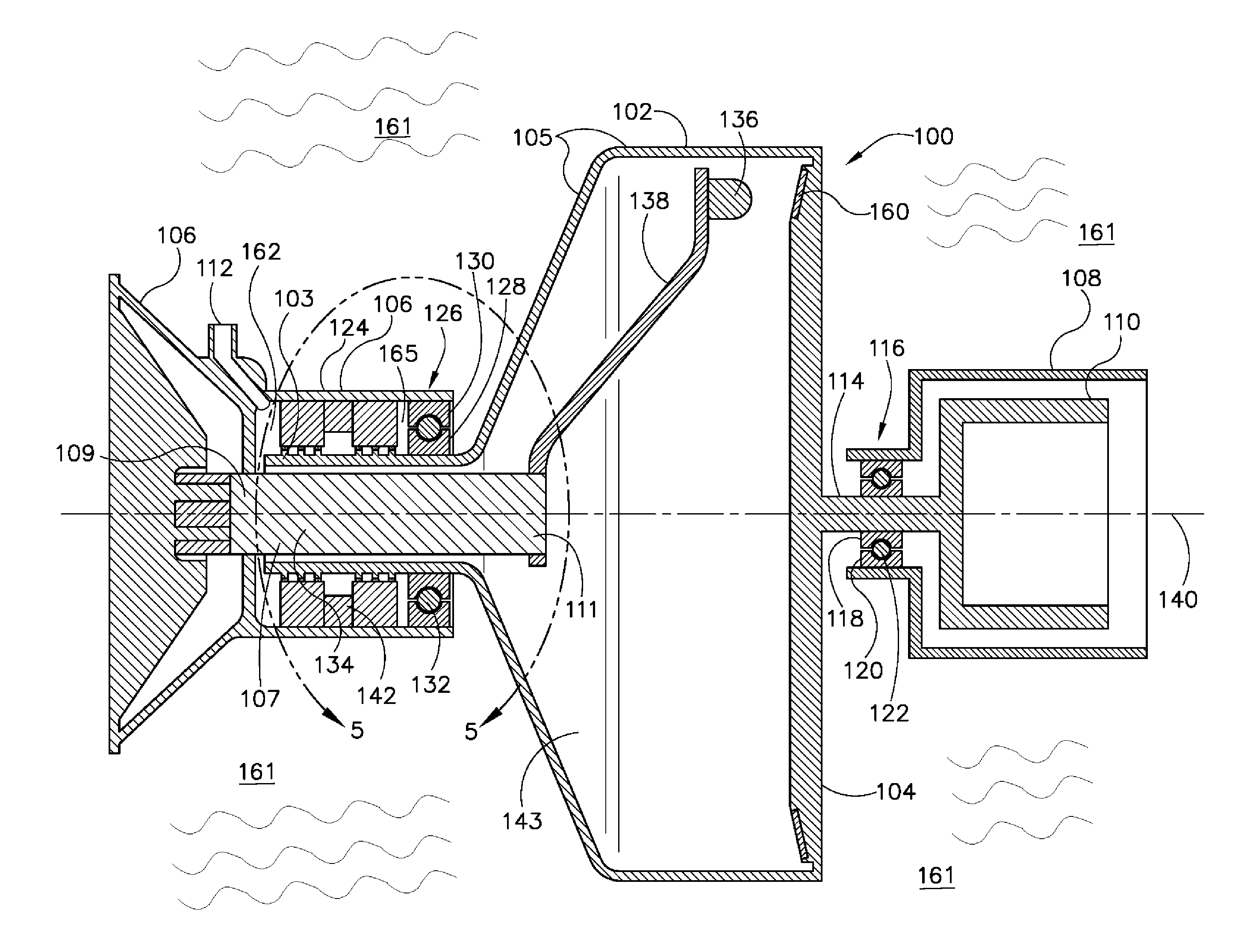
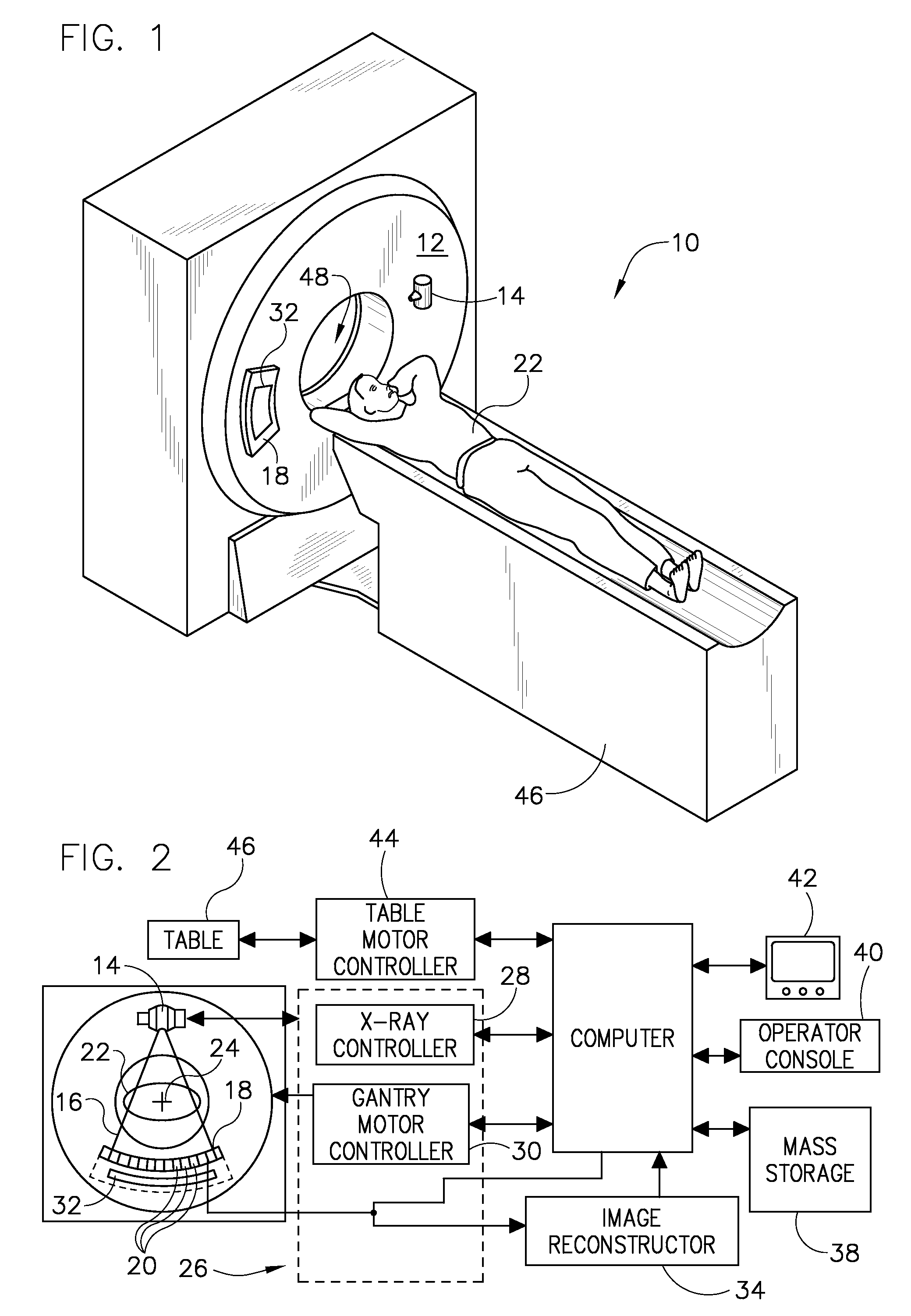
[0023]The operating environment of the present invention is described with respect to the use of an x-ray tube as used in a computed tomography (CT) system. However, it will be appreciated by those skilled in the art that the present invention is equally applicable for use in other systems that require the use of an x-ray tube. Such uses include, but are not limited to, x-ray imaging systems (for medical and non-medical use), mammography imaging systems, and radiographic (RAD) systems.

[0024]Moreover, the present invention will be described with respect to use in an x-ray tube. However, one skilled in the art will further appreciate that the present invention is equally applicable for other systems that require operation of a bearing in a high vacuum, high temperature, and high contact stress environment, wherein the life, reliability, or performance of the x-ray tube could benefit from placement of a bearing outside the vacuum region of the x-ray tube. The present invention will be ...


PUM


Abstract

An x-ray tube includes a stationary base and a passage therein. The x-ray tube includes an anode frame having an anode positioned adjacent to a first end and having a neck at a second end, the neck extends into the passage, wherein the anode frame is configured to rotate about a longitudinal axis of the passage. A hermetic seal is positioned about the neck between the neck and the stationary base.

Description

BACKGROUND OF THE INVENTION[0001]The present invention relates generally to x-ray tubes and, more particularly, to a method of fabricating and an apparatus of a rotating frame x-ray tube having a stationary cathode radially offset from a center of rotation thereof, and having a target and cathode hermetically sealed from an ambient environment.[0002]X-ray systems typically include an x-ray tube, a detector, and a rotating assembly to support the x-ray tube and the detector. In operation, an imaging table, on which an object is positioned, is located between the x-ray tube and the detector. The x-ray tube typically emits radiation, such as x-rays, toward the object. The radiation typically passes through the object on the imaging table and impinges on the detector. As radiation passes through the object, internal structures of the object cause spatial variances in the radiation received at the detector. The detector converts received radiation to electrical signals, and the x-ray sys...

Claims


Application Information

Patent Timeline
Patent Type & Authority Patents(United States)
IPC IPC(8): H01J35/20H01J35/10H01J35/12
CPCH01J35/06H01J35/101H01J35/16H01J35/305H01J2235/1216H01J2235/1006H01J2235/1046H01J35/1024
Inventor SCHAEFER, THOMAS D.HOCKERSMITH, RON KENT
Owner GENERAL ELECTRIC CO
Why Eureka
Try Eureka