Energy-saving control in image processing apparatus

a control and image processing technology, applied in process and machine control, digital output to print units, instruments, etc., can solve the problems of poor performance, complex control, and change of driver workload, and achieve the effect of reducing power consumption of image processing apparatus and maintaining permeability of command data inpu

Inactive Publication Date: 2009-07-14
CANON KK
View PDF13 Cites 12 Cited by
  • Summary
  • Abstract
  • Description
  • Claims
  • Application Information

AI Technical Summary

Benefits of technology

[0010]The present invention has been made in consideration of the above situation, and has as its object, in an image processing apparatus where an external interface and an internal interface are matched in units of logical channels, to reduce power consumption of the image processing apparatus in the energy-saving mode, while maintaining permeability of command data inputted from an external data processing apparatus.

Problems solved by technology

Therefore, there are large problems in terms of an alteration workload of a driver which is installed in the data processing terminal, complexity of the control, and a throughput.
Since command data from a data processing terminal is always analyzed by the main controller of the image processing apparatus as described above, there are large problems in terms of poor performance due to the analysis performed by the data processing terminal, and a program design for the analysis.
However, in the above-described methods, power consumption of the respective functions, such as a printer, a scanner, or the like, of the image processing apparatus in the energy-saving mode is not always kept low.
Therefore, if each function of the image processing apparatus does not have the automatic power resume feature, in a case of a power-off state, the function whose power is turned off cannot receive the command.
However, if the automatic power resume feature is provided to each of the functions, power is consumed even in the energy-saving mode as described above.

Method used


Image

  • Energy-saving control in image processing apparatus
  • Energy-saving control in image processing apparatus
  • Energy-saving control in image processing apparatus

Examples


Embodiment Construction

[0027]A preferred embodiment of the present invention will now be described in detail in accordance with the accompanying drawings.

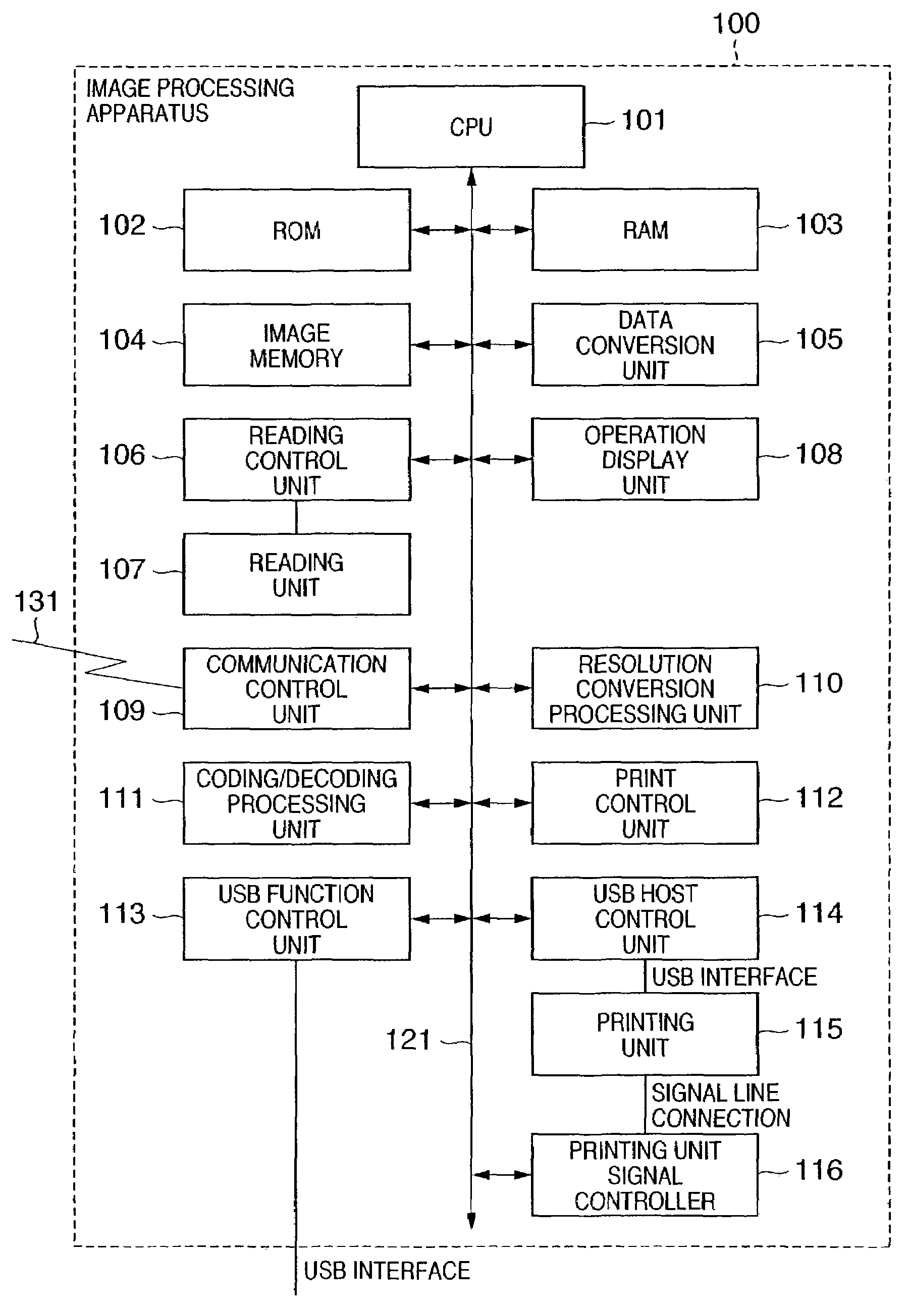
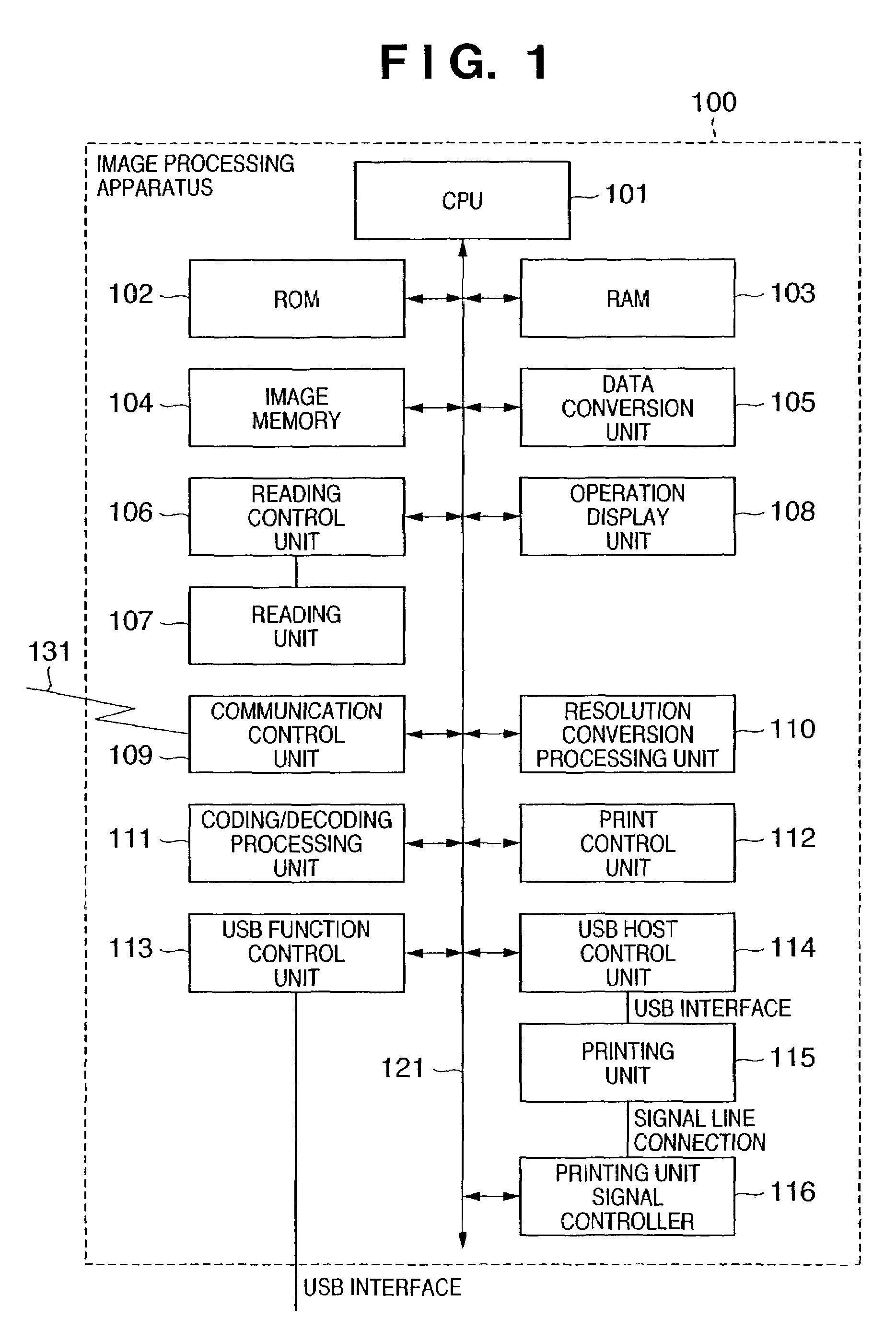
[0028]First, a brief construction of an image processing apparatus 100, which constitutes an image processing system according to the embodiment of the present invention, is described in detail with reference to FIG. 1.

[0029]In the image processing apparatus 100, a CPU 101 serving as a system control unit controls the entire image processing apparatus 100. ROM 102 stores control programs and an incorporated operating system (OS) program or the like, which are executed by the CPU 101. In this embodiment, each of the control programs stored in the ROM 102 realizes software controlling, e.g., scheduling, task switch and so on, under the control of the incorporated OS stored in the ROM 102.

[0030]RAM 103, configured with SRAM (static RAM) or the like, stores program control variables or the like, and set values registered by an operator as well as control dat...


PUM


Abstract

An image processing apparatus comprising a data processing unit; a first interface unit, having a plurality of logical channels, adapted to connect with an external processing apparatus; a second interface unit, compliant with a same communication standard as the first interface unit and having a plurality of logical channels with a different configuration from the first interface unit, adapted to connect with the data processing unit; a control unit adapted to control overall operation of the image processing apparatus and data transfer between the first interface unit and the second interface unit; a power control unit adapted to control turning ON / OFF power supply to the data processing unit; and a signal line connected to the data processing unit, with which the power control unit controls the data processing unit to turn on when the data processing unit is turned off and is not provided with an automatic power resume feature.

Description

FIELD OF THE INVENTION[0001]The present invention relates to energy-saving control in an image processing apparatus.BACKGROUND OF THE INVENTION[0002]Conventionally, there are multi-function image processing apparatuses having a plurality of functions, such as a printer, a scanner, facsimile communication and the like, which are capable of connecting with a data processing terminal, such as a personal computer (PC). Each of the functions of the image processing apparatus can be controlled independently by the data processing terminal. However, to simultaneously operate these functions so as to fully take advantage of the plurality of functions, the following workload is necessary. First of all, in the data processing terminal, it is necessary to add header information, which specifies a function such as a printer, a scanner, facsimile communication or the like, to the head of an intended control command, edit and packet the data, and transmit the packeted data to the image processing...

Claims


Application Information

Patent Timeline
Patent Type & Authority Patents(United States)
IPC IPC(8): G06K15/00B41J29/38G06F1/26G06F1/32G06F3/12H04N1/00
CPCG06K15/00G06K15/1822G06K15/1803
Inventor FUJINAGA, SEIYAIMAI, TAKASHI
Owner CANON KK
Why Eureka
Try Eureka