
Image processing apparatus and method, and program

a technology of image processing and apparatus, applied in the field of image processing apparatus and method, and program, can solve the problems of no advantages, no artifacts generated due, and imperfect roughly isotropic images to be constructed

Inactive Publication Date: 2009-07-21
CANON KK
View PDF13 Cites 19 Cited by
  • Summary
  • Abstract
  • Description
  • Claims
  • Application Information

AI Technical Summary

Benefits of technology

The present invention provides an image processing apparatus and method for accurately and quickly determining and outputting diagnostic images including a diagnostic pathology from subject images. The apparatus includes a detection system for detecting nodules in a radiation image of a subject, and a calculation system for calculating a feature amount of the image. The apparatus can generate a first cross section image and a second cross section image of the subject, where the second cross section image includes the nodule detected in the first cross section image. The apparatus can also calculate the circularity of the nodule in the second cross section image as the feature amount. The apparatus can output a diagnostic image including the nodule detected in the detection step on the basis of a determination result. The invention also provides a program for implementing the image processing method. The technical effects of the invention include improved accuracy and efficiency in diagnostic image processing.

Problems solved by technology

For this reason, artifacts are generated due to connection errors in the body axis direction if multi-planar reconstruction is made.
In Multi detector row spiral CT in recent years, roughly isotropic images can be constructed but are not perfect since spiral scan is done.
On the other hand, since vein branches in lungs normally run in the up-and-down direction, a roughly circular nodule detected from an axial image is readily mistaken for a vein, resulting in no advantages.

Method used


Image

  • Image processing apparatus and method, and program
  • Image processing apparatus and method, and program
  • Image processing apparatus and method, and program

Examples


Embodiment Construction

[0070]Preferred embodiments of the present invention will now be described in detail in accordance with the accompanying drawings.

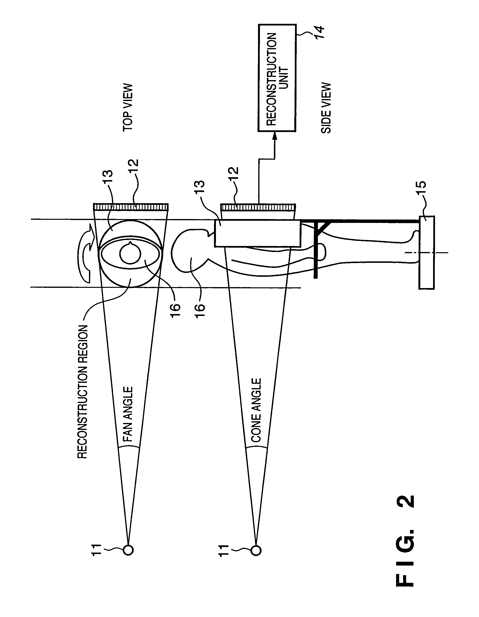
[0071]The present invention relates to a radiation image sensing technique for imaging a radiation distribution in a subject using radiation such as an X-ray CT apparatus that makes an image using radiation such as X-rays and the like. More particularly, the present invention relates to a cone beam CT apparatus having a computer diagnosis aiding function or an image processing technique having a computer-aided diagnosis processing function from cone beam CT images.

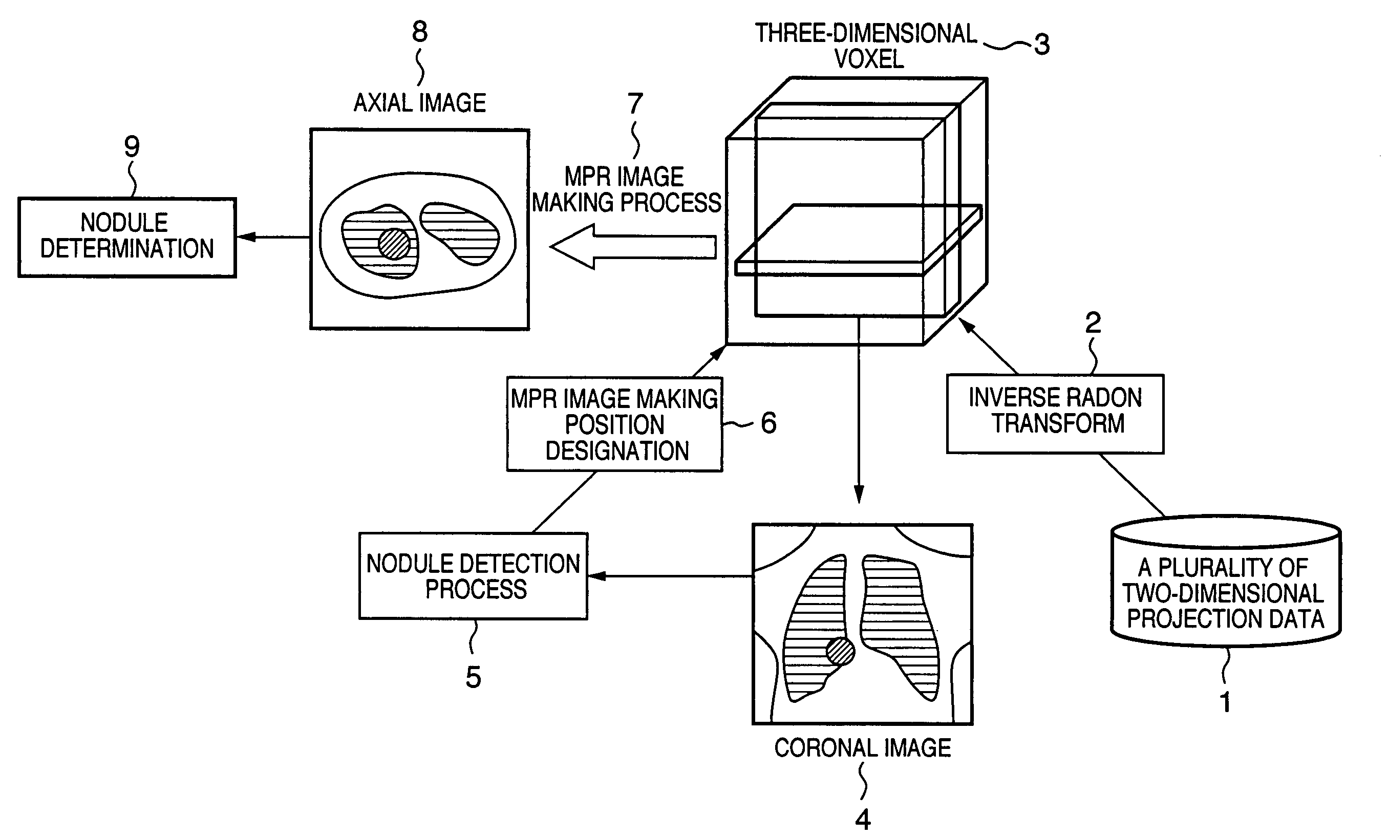
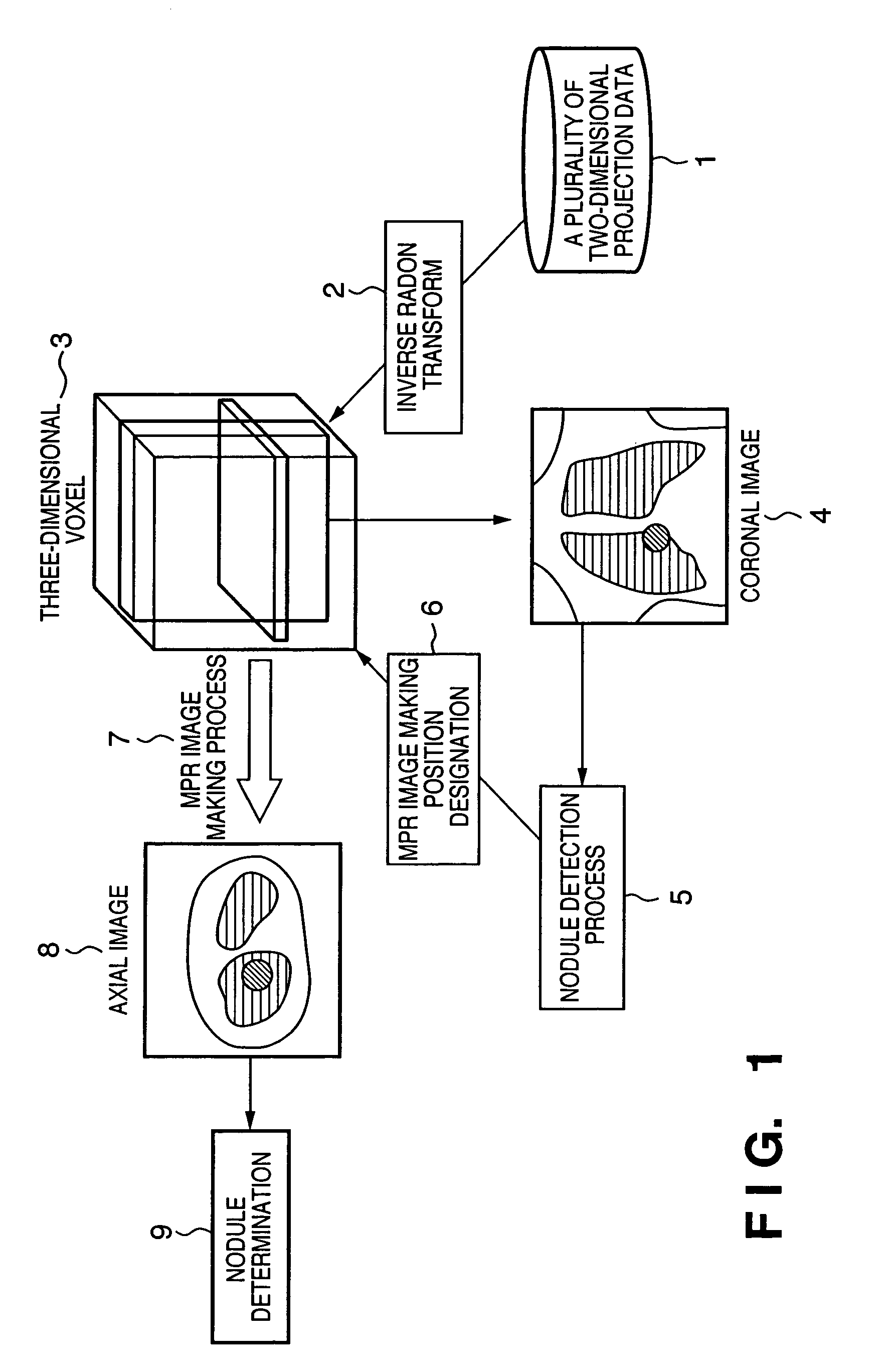
[0072]FIG. 1 is a schematic view for explaining the overall picture of an image processing system according to the present invention.

[0073]For example, a 3D voxel 3 as a 3D image of a subject is reconstructed by computing inverse radon transforms (2) of a plurality of 2D projection data through 360° (or 180°+fan angle) of the subject obtained from a CBCT imaging apparatus.

[0074]In FIG. 1, images...


PUM

PropertyMeasurementUnit
partial angleaaaaaaaaaa
fan angleaaaaaaaaaa
sizeaaaaaaaaaa

Abstract

A first cross section image other than an axial image of a subject is generated from a radiation image. A nodule in the first cross section image is detected. A second cross section image including the detected nodule is generated from the radiation image. A feature amount of the second cross section image is calculated. It is determined based on the calculated feature amount whether not the detected nodule is a diagnostic pathology. A diagnostic image including the detected nodule is output on the basis of the determination result.

Description

FIELD OF THE INVENTION[0001]The present invention relates to an image processing apparatus and method for processing a radiation image of a subject acquired utilizing radiation, and outputting a diagnostic image, and a program.BACKGROUND OF THE INVENTION[0002]Conventionally, an X-ray CT apparatus which irradiates a subject with X-rays, detects X-rays transmitted through or scattered by the subject using an X-ray detector, and makes a fluoroscopic image, tomosynthesis, or three-dimensional (3D) image on the basis of this X-ray detection output (the number of photons of X-rays) is known.[0003]As such X-ray CT apparatus, a cone beam CT apparatus has been developed. In a normal X-ray CT apparatus, an X-ray beam is limited to be thin in the Z-direction, and is called a fan beam. However, cone beam CT (CBCT) uses an X-ray beam which also spreads in the Z-direction, and is called a cone beam.[0004]In multi-slice CT or CBCT, images are generated in large quantities as imaging results. Hence...

Claims


Application Information

Patent Timeline
Patent Type & Authority Patents(United States)
IPC IPC(8): G06K9/00A61B6/00A61B6/03G01N23/00G01N23/04G06T1/00G06T7/00G21K1/12H05G1/60
CPCA61B6/032G01N23/046G06T7/0012G01N2223/612G06T2207/30061G01N2223/419A61B6/5217A61B6/5223G16H50/30
Inventor TSUJII, OSAMU
Owner CANON KK
Learn More