
Image acquisition and processing methods for automatic vehicular exterior lighting control

a technology for automatic vehicular exterior lighting and image acquisition, applied in adaptive control, digital computer details, instruments, etc., can solve the problems of difficult to distinguish between oncoming vehicle head lamps and reflections of the controlled vehicle's head lamps off signs or other objects, and achieve the effect of facilitating training

Active Publication Date: 2009-07-21
GENTEX CORP
View PDF70 Cites 364 Cited by
  • Summary
  • Abstract
  • Description
  • Claims
  • Application Information

AI Technical Summary

Benefits of technology

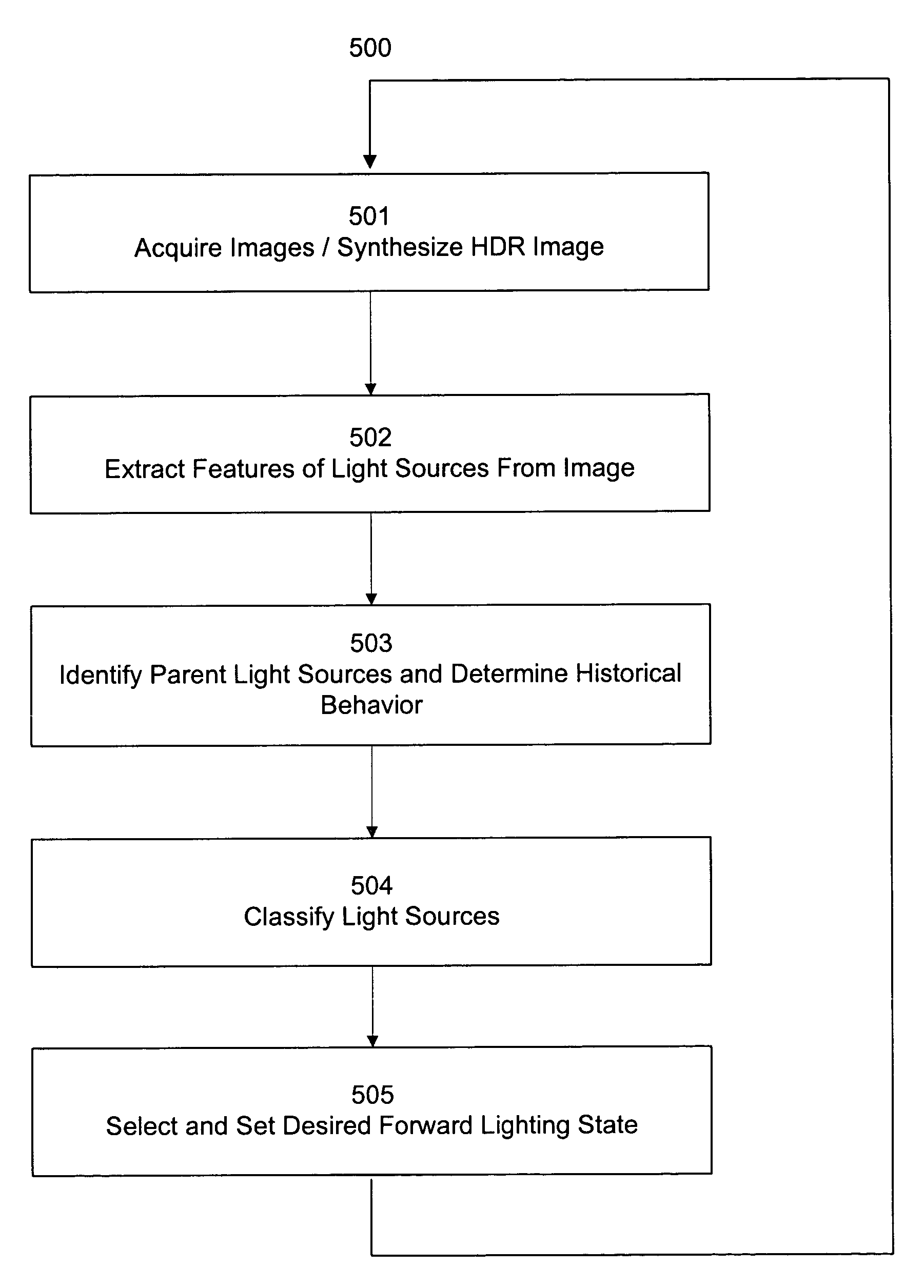
The present invention provides an apparatus for acquiring and processing images of a scene, as well as a low-voltage differential signal device for interface of an imager to a microprocessor. Additionally, the invention provides a method for synthesizing high dynamic range images to accommodate the diverse brightness levels associated with various light sources anticipated to be present in the associated field of view of the imager. The invention also provides a peak detect algorithm for separately detecting light sources that are very close together and, or, partially overlapping, and light source classification algorithms for identifying light sources that induce system responses. Furthermore, the invention provides switching methods for automatically varying the operation of exterior vehicle lights, such as bi-modal, substantially continuously variable, and continuously variable lights. Finally, training routines are provided for calibration of the classification algorithms, which may involve various techniques such as empirical, experimental, real time, and statistical data.

Problems solved by technology

Light source detection within image sensing presents many challenges.
For example, it may be difficult to discriminate between oncoming vehicle head lamps and reflections of the controlled vehicle's head lamps off of signs or other objects.
Additionally, it may be difficult to detect distant tail lamps in proximity of other light sources, such as overhead street lamps for example, because these light sources may blur together in the image diluting the red color of the tail lamps.
However, construction of such a system requires a more expensive image sensor, a high quality lens, more processing power and more memory which, at the present time, would be cost prohibitive.
Further more, not all of the problems with currently disclosed systems are likely to be solved with increased resolution alone, even disregarding economics.

Method used


Image

  • Image acquisition and processing methods for automatic vehicular exterior lighting control
  • Image acquisition and processing methods for automatic vehicular exterior lighting control
  • Image acquisition and processing methods for automatic vehicular exterior lighting control

Examples


Embodiment Construction

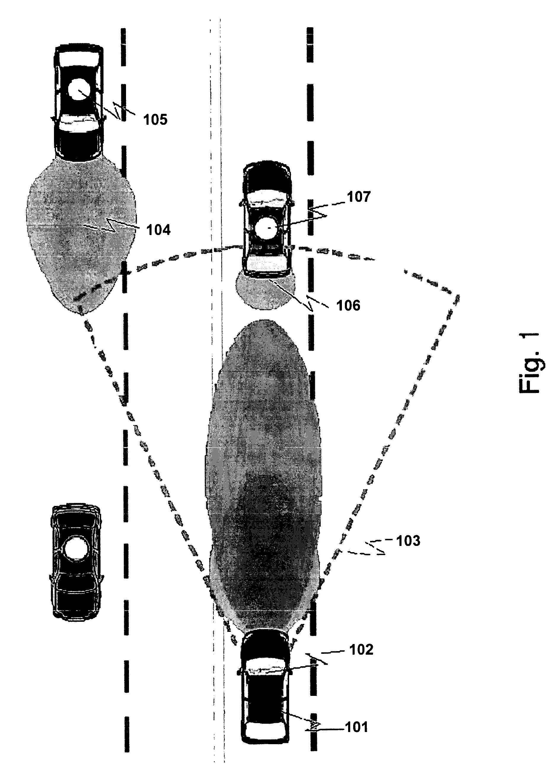
[0032]The functionality of the current invention is best described with initial reference to FIG. 1. A controlled vehicle 101 contains an imager and an image processing system that is capable of acquiring and analyzing images of the region generally forward of the controlled vehicle. The imager and image processing system are preferably contained in the controlled vehicle's rear view mirror assembly 102, thus providing a clear forward view 103 from a similar perspective as the driver through the windshield in the region cleaned by the windshield wipers. The imager may alternatively be placed in any suitable position in the vehicle and the processing system may be contained with the imager or positioned elsewhere. A host of alternate configurations are described herein, as well as, within various incorporated references. The image analysis methods described herein may be implemented by a single processor, such as a microcontroller or DSP, multiple distributed processors, or may be im...


PUM


Abstract

The present invention relates to various apparatus, algorithms and methods for acquiring and processing images of a scene. Details of various aspects of the associated images are identified and may be utilized to generate various vehicular equipment control signals.

Description

CROSS-REFERENCE TO RELATED APPLICATIONS[0001]This application claims priority under 35 U.S.C. 119(e) to provision U.S. Patent Application Ser. No. 60 / 404,879, entitled “IMAGE ACQUISITION AND PROCESSING METHOD FOR VEHICULAR LIGHTING CONTROL,” filed on Aug. 21, 2002, Joseph S. Stam et al. The disclosure of which is hereby incorporated in its entirety by reference.BACKGROUND OF THE INVENTION[0002]It has long been desirable to provide automatic control of vehicle lighting both to improve driving safety and provide convenience for the driver. Such automatic lighting control may include automatic activation and deactivation of a controlled vehicle's high beam headlights as a function of driving conditions. This function has been widely attempted using various types of optical sensors to detect the ambient lighting conditions, the head lamps of oncoming vehicles and the tail lamps leading vehicles. Most recently, sensors utilizing an electronic image sensor have been proposed. Such systems...

Claims


Application Information

Patent Timeline
Patent Type & Authority Patents(United States)
IPC IPC(8): G06K9/62B60Q1/02G05B13/02G06E1/00B60Q1/08B60Q1/14B60Q1/18G06K9/00H05B37/02
CPCB60Q1/085B60Q1/18G06K9/00825H05B37/02B60Q1/143B60Q2300/052B60Q2300/054B60Q2300/056B60Q2300/112B60Q2300/122B60Q2300/132B60Q2300/134B60Q2300/21B60Q2300/312B60Q2300/314B60Q2300/322B60Q2300/331B60Q2300/332B60Q2300/3321B60Q2300/41B60Q2300/42H05B47/17H05B47/165G06V20/584Y02B20/40G06F7/00
Inventor STAM, JOSEPH S.MART, GREGORY A.BERENDS, KEITH H.BUSH, GREGORY S.ROBERTS, JOHN K.PIERCE, MARK W.BECHTEL, JON H.WALSTRA, ERIC J.RYCENGA, BROCK R.
Owner GENTEX CORP
Learn More