
Hazardous material storage building

a technology for hazardous materials and storage buildings, applied in the directions of transportation and packaging, parkings, packaging, etc., can solve the problems of gases and vapors being subject to the force of air currents

Inactive Publication Date: 2009-07-28
HAZ SAFE
View PDF24 Cites 12 Cited by
  • Summary
  • Abstract
  • Description
  • Claims
  • Application Information

AI Technical Summary

Benefits of technology

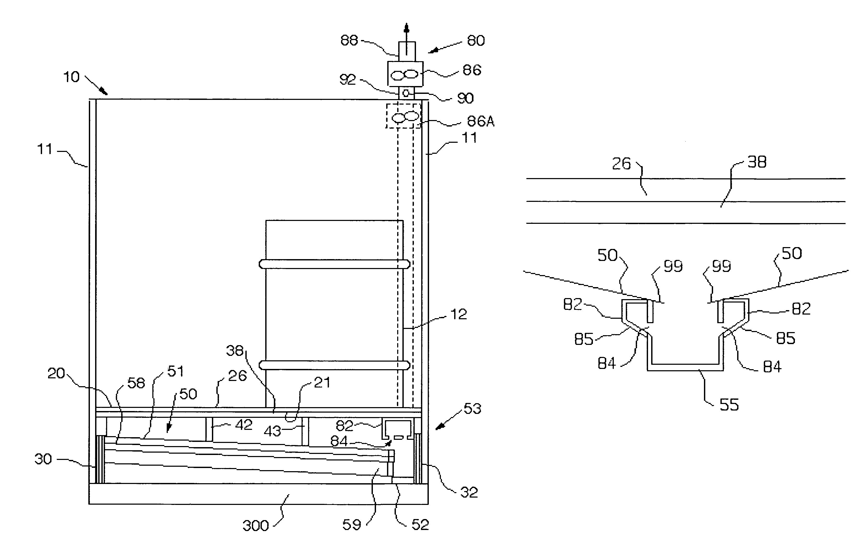
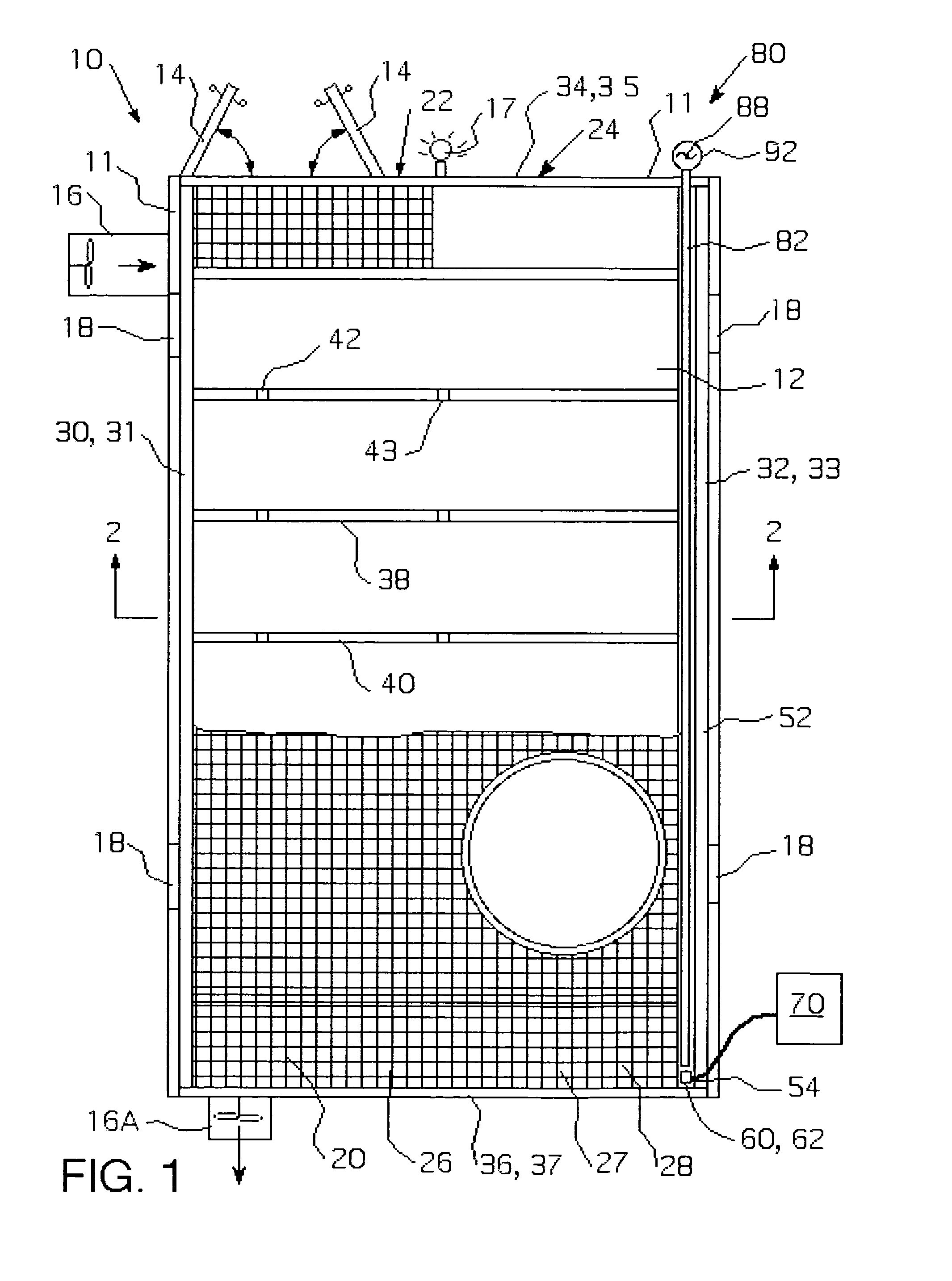
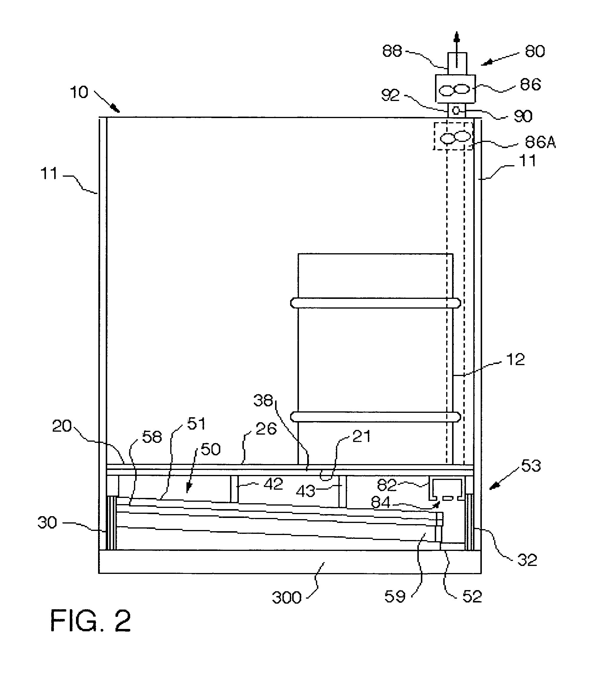
[0011]In operation, the hazardous vapor detection system generally draws air from the hazardous material storage facility downwardly through the hazardous material storage facility to the area below the upper floor. Air between the upper floor and the lower floor is also drawn through the vent openings and passed over the vapor sensor before being expelled. Because a leaked hazardous material is likely to have fallen through the upper floor onto the lower floor, the hazardous vapor will be more concentrated adjacent to the lower floor. The concentrated vapors are also drawn through the vent openings and passed over the vapor sensor before being expelled. Because the hazardous vapors are concentrated, the vapor sensor of the present invention is more likely to detect a smaller quantity of hazardous vapors. A smaller quantity of hazardous vapor is typically associated with a smaller leak of hazardous materials. Additionally, because the hazardous vapor detection system of the present invention draws the air in the hazardous material storage facility downwardly, a worker in the upper area of the hazardous material storage facility is less likely to be exposed to hazardous vapor from hazardous material spilled on the lower floor.
[0013]An additional advantage of the present system is that the intake fan may be disposed at any location in the facility. That is, because the air and fumes are being drawn downwardly, the intake fan does not have to direct air flow across the floor. Moreover, because the air flow is towards the lower floor, the flow pattern created by the intake and exhaust fans is not affected by additional openings in the facility walls, e.g., an open door. That is, if a door is accidentally left open, air will merely flow through the door, down to the lower floor and exit the facility through the hazardous vapor detection system.

Problems solved by technology

Similarly, heavier than air gases will tend to flow to the low point, however, gases and vapors are also subject the force of air currents.

Method used


Image

  • Hazardous material storage building
  • Hazardous material storage building
  • Hazardous material storage building

Examples


Embodiment Construction

[0026]A metal hazardous material storage facility 10 according to the present invention is shown in FIGS. 1 and 2. Although a facility 10 of any shape may be used with this invention, in the preferred embodiment, the facility 10 has a rectangular floor plan having a length and a width. The facility 10 incorporates a dual floor structure which includes an upper floor 20 and a lower floor 50 which are both disposed above a foundation 300. The facility 10 further includes lateral walls 11 extending generally vertically from foundation 300, doors 14 in walls 11, as well as safety features such as, an intake fan 16 for providing positive pressure into the facility 10, warning lights 17, emergency vents 18 and may include an emergency exhaust fan 16A. These elements are well known in the prior art. The safety features may be controlled by the spill detection system 70 (shown hereinafter) according to a predetermined protocol.

[0027]The upper floor 20 is divided into an aisle portion 22 and...


PUM


Abstract

A hazardous material storage facility is provided that includes an upper floor having openings therethrough, a lower floor that is sloped from an upper end to an elongated basin, at least one vent duct disposed beneath the upper floor and adjacent to the lower floor basin, the vent duct including vent openings structured to allow air and fumes to be introduced into the vent duct and a means for removing the air and fumes in the vent duct therefrom. In this configuration, air is drawn generally downwardly through the facility while hazardous vapors, which typically emanates from spilled hazardous materials on the lower floor, are located close to the vent duct.

Description

FIELD OF INVENTION[0001]This invention relates to a hazardous material storage facility or a modular hazardous material storage facility and, more specifically, to a hazardous material storage facility having a vent system with a sensor disposed below the container supporting floor.BACKGROUND OF THE INVENTION[0002]Commonly owned U.S. Pat. Nos. 6,305,131; 6,223,473; 5,396,742; 5,301,479; and 5,285,617, all of which are expressly incorporated by reference herein, disclose various hazardous material storage buildings and features thereof.[0003]Hazardous materials, such as chemicals or waste in either a solid or liquid form, are frequently placed in 55-gallon cylindrical barrels. These drums are typically further stored in a storage facility. Such drums, however, can easily develop leaks over time. Accordingly, these barrels must be kept in a facility that has suitable safety features such as proper venting, fire and explosion protection, leakage protection with a sump built into the fl...

Claims


Application Information

Patent Timeline
IPC IPC(8): E04H1/00
CPCE04H5/02
Inventor ROMIG, FREDERICK W.
Owner HAZ SAFE
Learn More