Multi-spot ophthalmic laser probe

a laser probe and multi-spot technology, applied in the field of laser probes, can solve the problems of long time to cover the desired retinal area, loss of central vision, inability to see fine details, read, or recognize faces,

Active Publication Date: 2009-07-28
ALCON INC
View PDF73 Cites 36 Cited by
  • Summary
  • Abstract
  • Description
  • Claims
  • Application Information

AI Technical Summary

Problems solved by technology

This can result in loss of central vision, which entails inability to see fine details, to read, or to recognize faces.
It can take a long time to cover the desired retinal area with photocoagulated spots using a single-beam laser probe.
However, given a laser with limited laser beam power that is already operating at its maximum laser power setting, a multi-spot laser probe may not necessarily reduce the time required to create the desired laser burn spot pattern.

Method used


Image

  • Multi-spot ophthalmic laser probe
  • Multi-spot ophthalmic laser probe
  • Multi-spot ophthalmic laser probe

Examples


Embodiment Construction

[0029]Reference is now made in detail to the exemplary embodiments of the invention, examples of which are illustrated in the accompanying drawings. Wherever possible, the same reference numbers are used throughout the drawings to refer to the same or like parts.

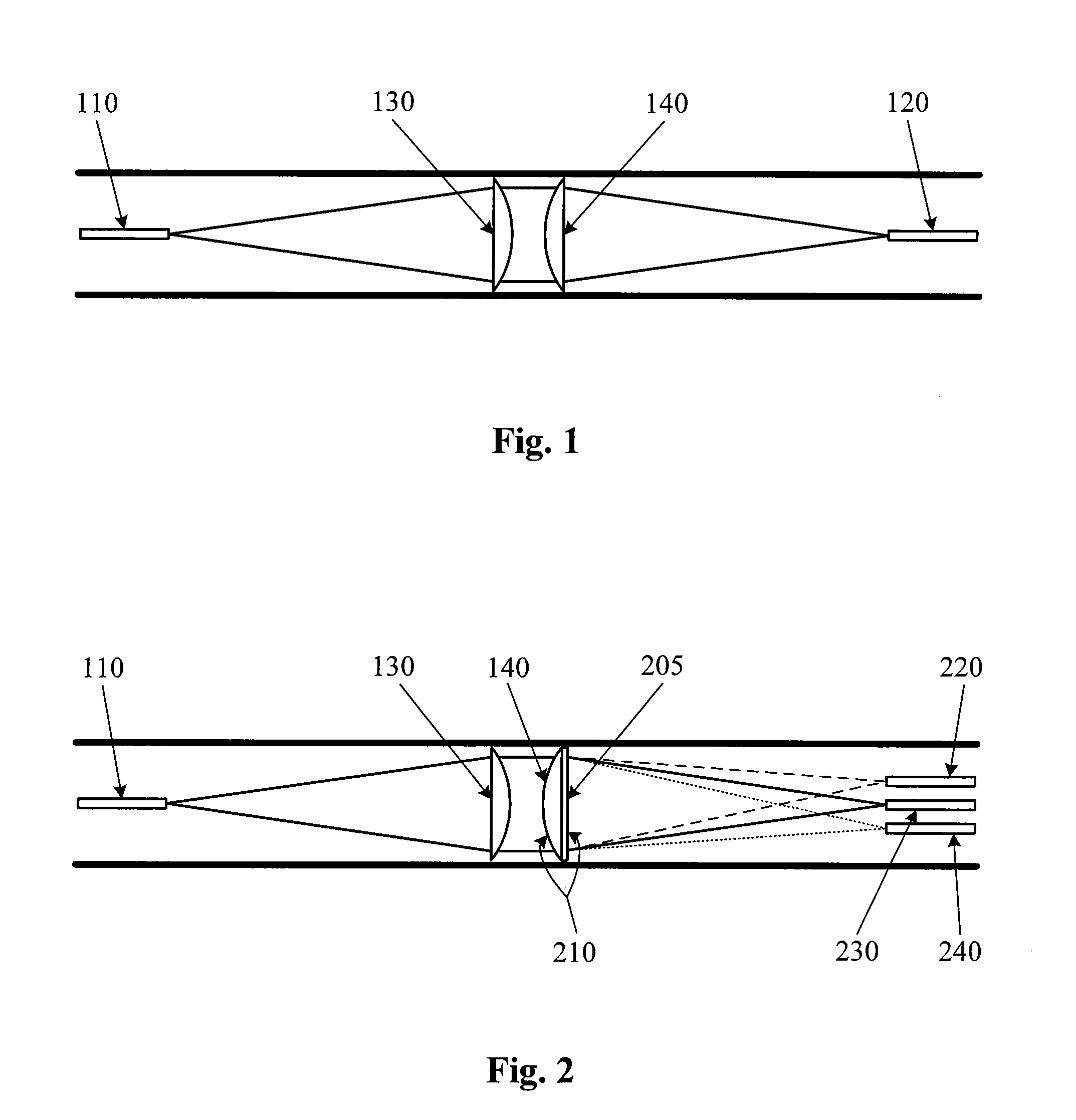
[0030]FIG. 1 is cross section view of a simple fiber to fiber imaging system consistent with the principles of the present invention. In the embodiment of FIG. 1, the system has two fibers 110, 120, and two lenses 130, 140. Fiber 110 emits a beam of diverging light that originates from a laser source (not shown). The diverging beam is collimated by lens 130. As is commonly known, collimated light is light whose rays are parallel with a planar wave front. This collimated beam is focused by lens 140 into a small diameter spot at the entrance face of receiving fiber 120. In this case, the lenses 130, 140 are each plano-convex aspheric lenses. In a plano-convex aspheric lens, one surface is planar and the other surface is convex...


PUM


Abstract

A laser probe includes an emitting optical fiber, optics, and two or more receiving optical fibers. The emitting optical fiber emits a beam of laser light. The optics diffract the beam of light emitted by the emitting optical fiber. The receiving optical fibers each receive a beam of light diffracted by the optics.

Description

BACKGROUND OF THE INVENTION[0001]The present invention relates to a laser probe for use in ophthalmic procedures and more particularly to a multi-spot laser probe for use in photocoagulation.[0002]Anatomically, the eye is divided into two distinct parts—the anterior segment and the posterior segment. The anterior segment includes the lens and extends from the outermost layer of the cornea (the corneal endothelium) to the posterior of the lens capsule. The posterior segment includes the portion of the eye behind the lens capsule. The posterior segment extends from the anterior hyaloid face to the retina, with which the posterior hyaloid face of the vitreous body is in direct contact. The posterior segment is much larger than the anterior segment.[0003]The posterior segment includes the vitreous body—a clear, colorless, gel-like substance. It makes up approximately two-thirds of the eye's volume, giving it form and shape before birth. It is composed of 1% collagen and sodium hyalurona...

Claims


Application Information

Patent Timeline
Patent Type & Authority Patents(United States)
IPC IPC(8): G02B6/42
CPCA61B18/22G02B27/1093G02B6/264G02B6/32G02B27/106A61F9/00821A61B2018/208A61B2018/2211A61B2018/2294A61B2019/5206A61F9/008A61F2009/00863A61N5/0603G02B5/1814A61B2090/306
Inventor AULD, JACK R.SMITH, RONALD T.
Owner ALCON INC
Why Eureka
Try Eureka