Liquid processing apparatus and liquid processing method

a technology of liquid processing apparatus and liquid processing method, which is applied in the direction of liquid surface applicators, pretreatment surfaces, coatings, etc., can solve the problems of cumbersome process of loading and unloading substrates, insufficient suppression of thickness at corner portions of polygonal substrates, and inability to meet the requirements of coating thickness, etc., to achieve uniform thickness of coated films.

Active Publication Date: 2009-07-28
TOKYO ELECTRON LTD
View PDF10 Cites 15 Cited by
  • Summary
  • Abstract
  • Description
  • Claims
  • Application Information

AI Technical Summary

Benefits of technology

[0008]It is therefore an object of the present invention to provide a liquid processing apparatus and method capable of ensuring a uniform thickness of a coated film.

Problems solved by technology

However, the conventional spin chuck cannot sufficiently suppress an increase in thickness at the corner portions of the polygonal substrate.
In addition, with a conventional spin chuck 100, a loading / unloading process of a substrate G is somewhat complicated.
In such a loading / unloading process, direct loading of the substrate G into the recess 101 is difficult to achieve, and thus such process of loading and unloading the substrate G may become cumbersome.
Furthermore, the time required in completing the series of such processes may deteriorate throughput.

Method used


Image

  • Liquid processing apparatus and liquid processing method
  • Liquid processing apparatus and liquid processing method
  • Liquid processing apparatus and liquid processing method

Examples


first embodiment

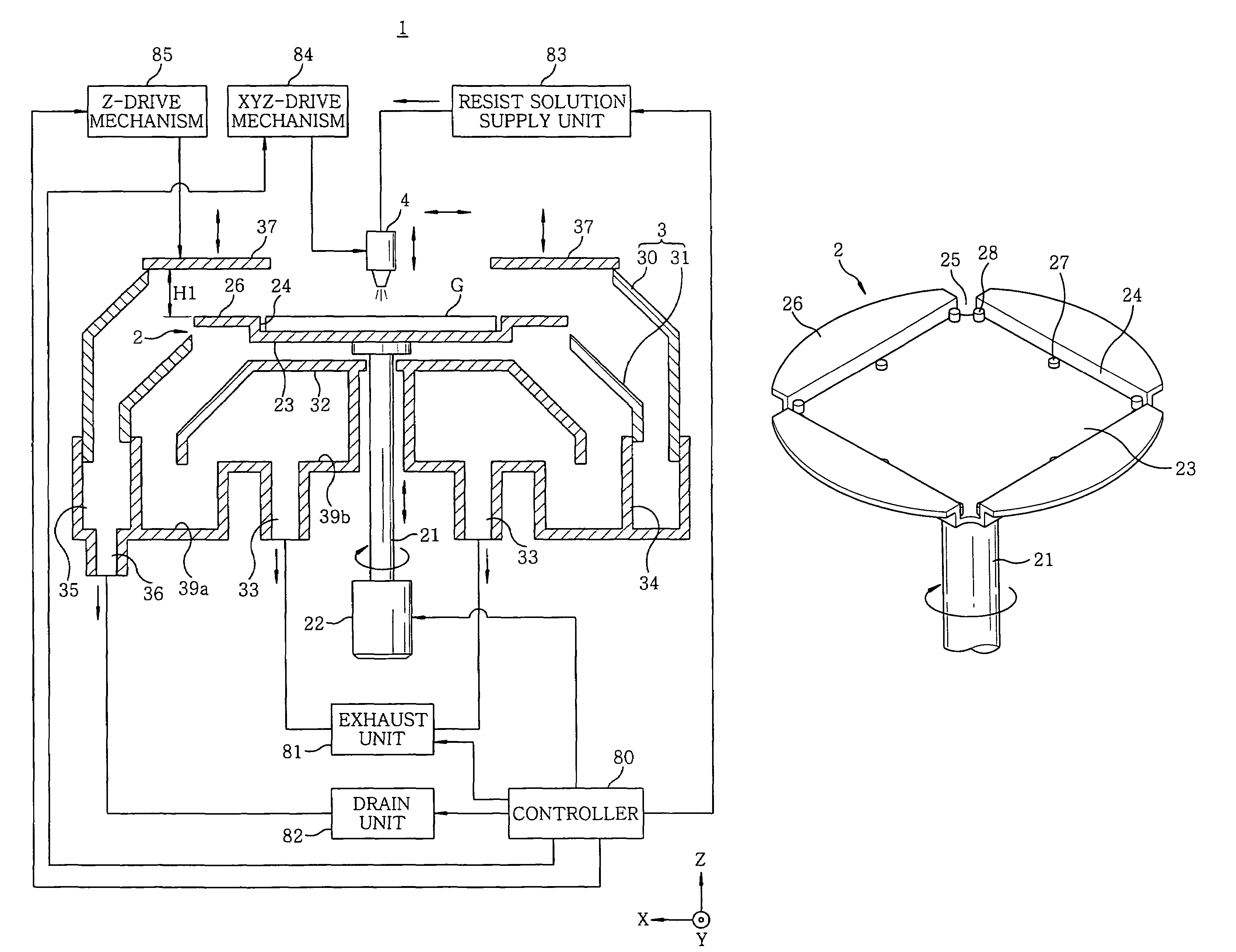
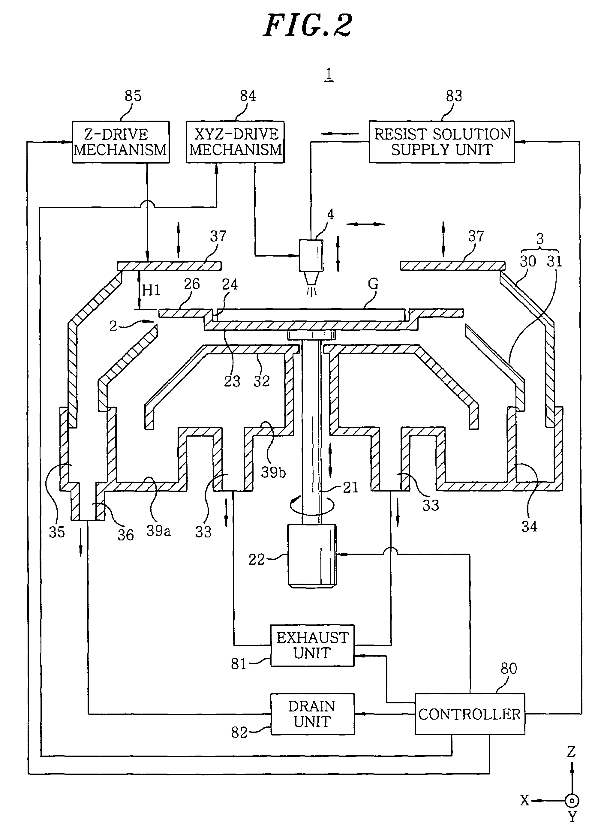
[0040]As shown in FIG. 2, a spin chuck 2 is accommodated in a cup 3 of a coating process apparatus 1. The spin chuck 2 receives a mask substrate G as a substrate to be processed from a transfer arm 5 (shown in FIGS. 5 and 8A to 8C) and a predetermined coating process is executed on the substrate G. The substrate G includes a chromium oxide (Cr2O3) coating film formed on a square quartz plate having a side (L1) of 152±0.4 mm and a resist layer formed thereon, wherein a plate thickness of the substrate G is ¼ inch (6.35±0.1 mm), and a projection length of a C face (13c in FIG. 7A) ranges from 0.2 to 0.6 mm.

[0041]The spin chuck 2 is provided with a support plate 23 and air flow control members 26. The support plate 23 includes upright walls 24 and a plurality of spacers 28 to secure the polygonal substrate G; and is connected with a driving member 22 via a rotation axle 21. The driving member 22 is controlled by a controller 80. The driving member 22 is capable of rotating the spin chu...

second embodiment

[0087]Hereinafter, a second embodiment of the present invention will be described with reference to FIG. 14. The description of parts that are similar to those in the first embodiment will be omitted.

[0088]A cup 6 employed in the second embodiment includes an air flow regulation ring 61 which is placed around an outer periphery of one or more air flow control members 26D of the spin chuck 2D, while maintaining a gap of, e.g., 2 mm therebetween. A flat top surface of the air flow regulation ring 61 is substantially parallel to the top surface of the air flow control members 26D. The air flow regulation ring 61 further includes bottom surface, the bottom surface having a flat inner portion and an outer portion slanted downwardly toward outside. Further, the top surface of the air flow regulation ring 61 is placed at a level slightly, e.g., 1 mm, higher than those of the air flow control members 26D. By surrounding the outer peripheries of the air flow control member 26D, the air flow ...

example 1

[0102]The present example employed the above-described method and the apparatus shown in FIG. 1 in forming a resist layer on a surface of a mask substrate G. First, the substrate G was mounted on a spin chuck and the resist solution film was formed in a high speed rotation process. The thinner contained in the resist solution was evaporated in a low speed rotation process to thereby obtain a resist layer.

[0103]A thickness of the resist layer formed on the surface of the substrate G was measured with a film thickness measuring device.

[0104]The process conditions were as follow:[0105](i) Dimensions of the substrate G: 152.4 mm×152.4 mm×6.35 mm(thickness)[0106](ii) Amount of coating solution supplied: 2 cc[0107](iii) High speed process: 2500 to 3200 rpm[0108](iv) Low speed process: 100 to 1000 rpm


PUM

PropertyMeasurementUnit
sizeaaaaaaaaaa
thicknessaaaaaaaaaa
thicknessaaaaaaaaaa

Abstract

In a liquid processing apparatus for forming a coating film on a polygonal substrate by spin coating in an ambient with a descending clean air flow, a spin chuck includes a support plate for substantially horizontally supporting the substrate thereon. Air flow control members are provided on the spin chuck such that the air flow control member being disposed adjacent to a periphery of the polygonal substrate supported on the spin chuck, wherein the air flow control member is not provided near corner portions of the substrate supported on the spin chuck. The liquid processing apparatus may includes an air flow regulation ring which is provided with an air inlet having an opening surrounding an outer periphery of the air flow control member, wherein the air inlet communicates with the exhaust unit.

Description

FIELD OF THE INVENTION[0001]The present invention relates to a liquid processing apparatus and method for use in a liquid process, e.g., a coating process forming a resist film, is performed by supplying a process liquid on a polygonal substrate such as a mask substrate (reticle) which is used upon an exposure process of photolithography.BACKGROUND OF THE INVENTION[0002]In a manufacture process of a semiconductor device or an LCD, a resist film forming process is photolithographically performed on a substrate to be processed. During such process, a mask substrate having a predetermined pattern lithographed thereon is employed in exposing the substrate to be processed. In order to lithographically form the mask pattern on the surface of the mask substrate, a series of steps are taken: first, a resist is spin coated on the mask substrate made of, e.g., glass, to thereby form a resist film; and then the resist film is exposed and developed, to thereby obtain a desired pattern.[0003]Dur...

Claims


Application Information

Patent Timeline
Patent Type & Authority Patents(United States)
IPC IPC(8): B05C5/02G03F7/16B05C11/08B05D1/00B05D1/40H01L21/00H01L21/027H01L21/687
CPCB05D1/005H01L21/6875H01L21/68721H01L21/68735H01L21/6715B05C11/08
Inventor KOBAYASHI, SHINJIMIYAMOTO, TETSUSHIHAMADA, MASAHITO
Owner TOKYO ELECTRON LTD
Why Eureka
Try Eureka