Method of powering up a plurality of loads in sequence

a technology of powering up a plurality of loads in sequence, applied in the field of lighting control system, can solve the problems of power distribution system being susceptible to abnormal operation, power distribution system may have a limited peak power capability, and undesired response in the operation of loads

Active Publication Date: 2009-07-28
LUTRON TECH CO LLC
View PDF31 Cites 101 Cited by
  • Summary
  • Abstract
  • Description
  • Claims
  • Application Information

AI Technical Summary

Benefits of technology

[0014]In addition, the present invention provides a load control system for controlling the amount of power delivered to a plurality of electrical loads from a power distribution system. The load control system comprises a plurality of load control devices. Each load control device is coupled to one of the plurality of electrical loads. The load control devices are operable to turn on each of the electrical loads in sequence in response to the AC power source powering up to prevent abnormal operation of the power distribution system.

Problems solved by technology

Power distribution systems are often susceptible to abnormal operation in response to the current drawn from the loads connected to the power distribution system.
For example, if all of the loads connected to the power distribution system power up concurrently and draw a large electrical current from the power distribution system, the magnitude and frequency of the output voltage of the power distribution system may fluctuate causing undesired responses in the operation of the loads.
First, the power distribution system may have a limited peak power capability.
For example, site supply generators have a substantially limited peak power capability as compared to utility-based generation.
Further, power distribution systems having a high source impedance are more susceptible to abnormal output performance.
When a lighting load is first turned on, the lighting load may draw a substantially large inrush current.
Accordingly, if the power distribution system powering the lighting control system is susceptible to abnormal operation as described above, the power distribution system may not be able to provide the appropriate power to start up the lighting control system when the lighting control system is energized such that all of the lighting loads turn on at once.
Further, a situation may occur in which the output voltage of the generator fluctuates as the lighting control system and all other loads powered by the generator attempts to power up at once.
If the generator is not able to provide the amount of current required by the large inrush current, the output voltage of the generator decreases in magnitude.

Method used


Image

  • Method of powering up a plurality of loads in sequence
  • Method of powering up a plurality of loads in sequence
  • Method of powering up a plurality of loads in sequence

Examples


first embodiment

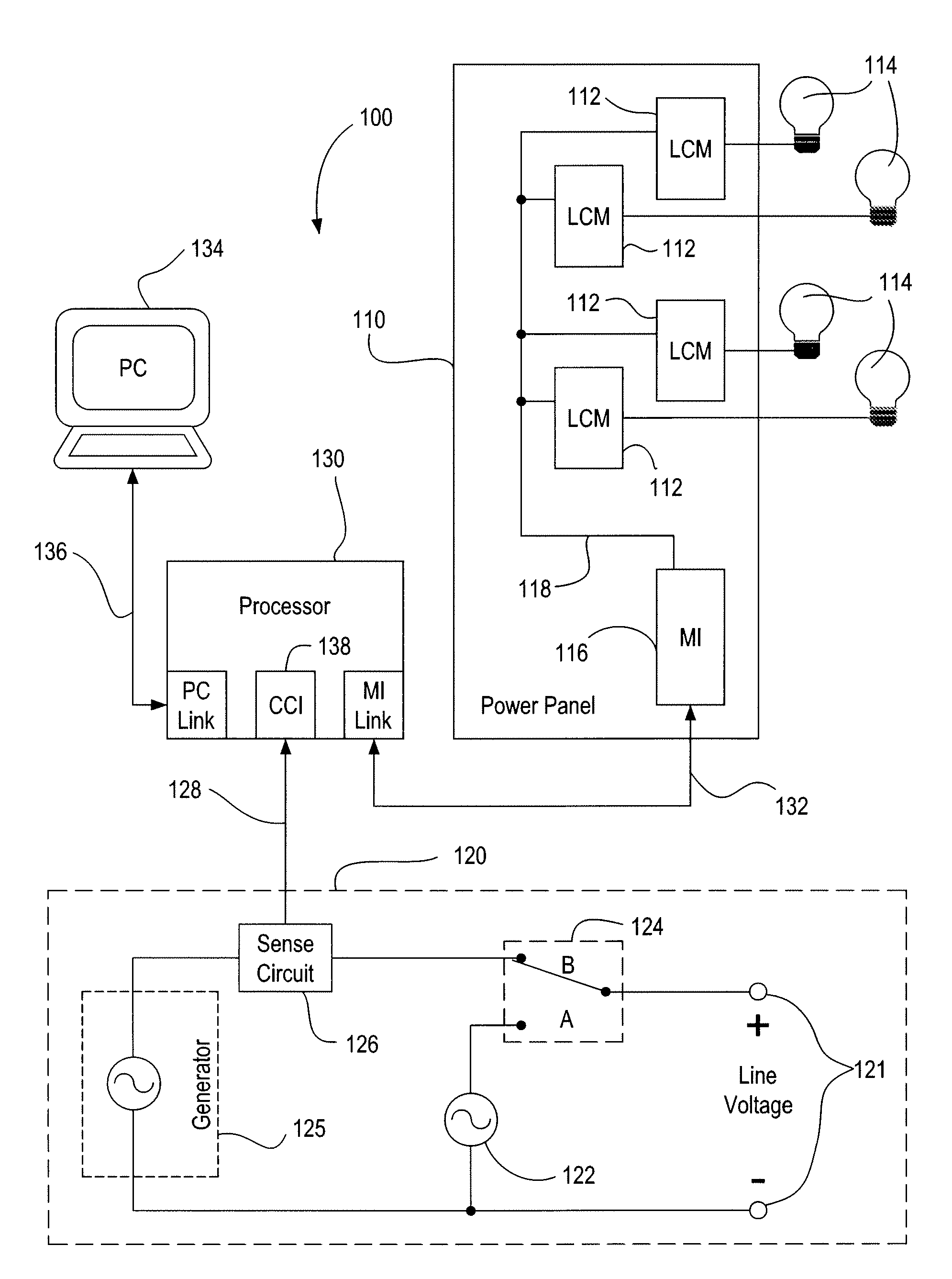
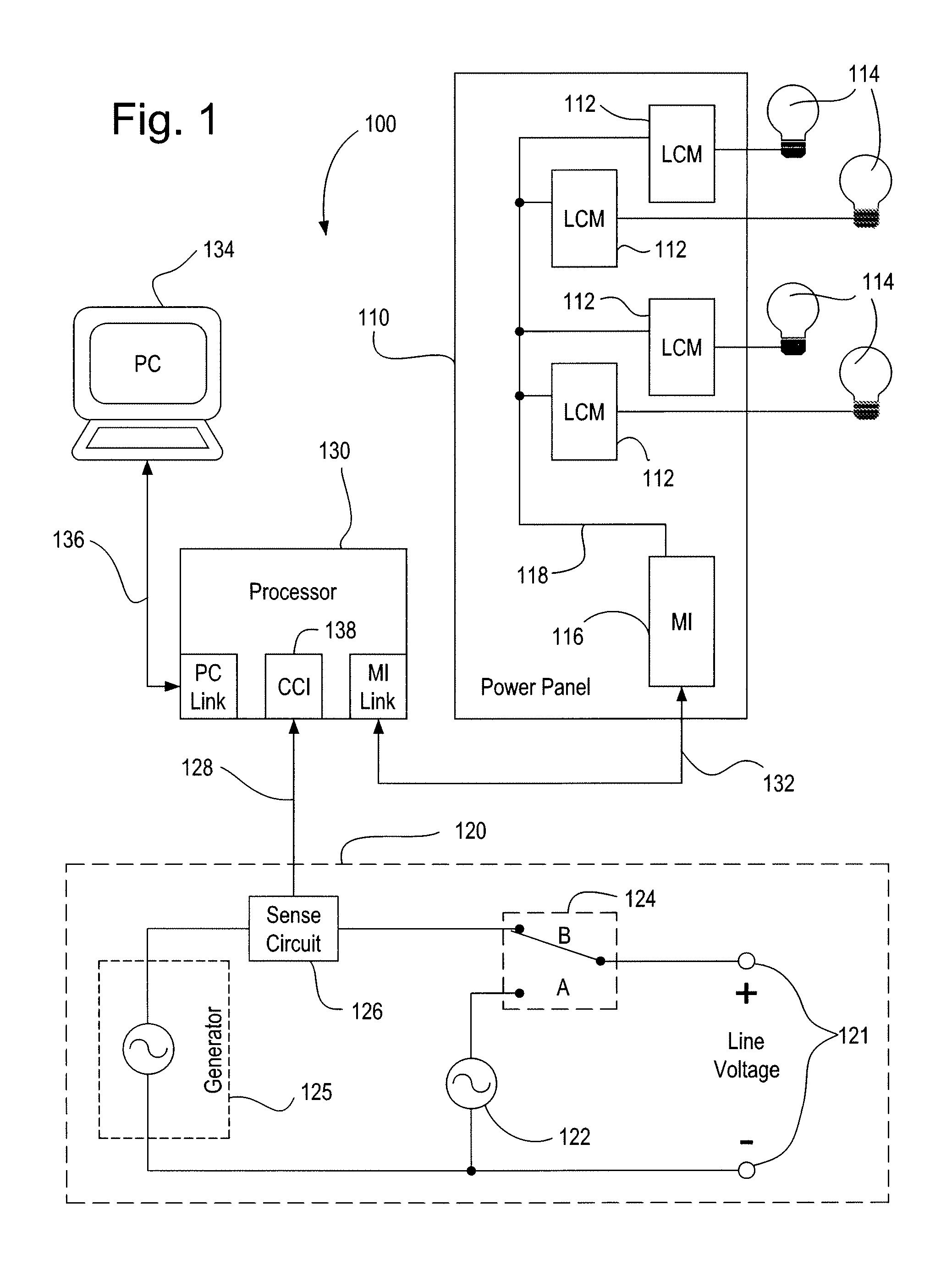
[0031]FIG. 1 is a simplified block diagram of a centralized lighting control system 100 according to the present invention. The lighting control system comprises a power panel 110 having a plurality of load control modules (LCMs) 112 (i.e., a load control device). Each load control module 112 is coupled to a lighting load 114 for control of the amount of power delivered to the lighting load. Alternatively, each load control module 112 may be coupled to more than one lighting load 114, for example, four lighting loads, for individually controlling the amount of power delivered to each of the lighting loads. The power panel 110 also comprises a module interface (MI) 116, which controls the operation of the load control modules 112 via digital signals transmitted across a power module control link 118.

[0032]A power distribution system 120 provides an output voltage (i.e., a line voltage, such as 120 V, 60 Hz) to the load control modules 112 via two line voltage connections 121. While n...

second embodiment

[0064]FIG. 8A is a simplified block diagram of a lighting control system 800 according to the present invention. The lighting control system 800 includes three central processors 830A, 830B, 830C, which are all connected to an interprocessor communication link 840 to allow for the transmission of digital messages (i.e., digital signals) between the central processors. Only one of the central processors (i.e., the first central processor 830A) includes the CCI 138 for receipt of the contact closure output signal 128 from the sense circuit 126 of the power distribution system 120. Upon detecting that the contact closure output signal 128 has been asserted, the first central processor 830A transmits a digital message representative of the CCI event (i.e., a “CCI status message”) to the other central processors 830B, 830C via the interprocessor communication link 840. Thus, to begin the startup sequence, the second and third central processors 830B, 830C do not respond to the contact cl...

third embodiment

[0069]FIG. 9 is a simplified block diagram of a distributed lighting control system 900 according to the present invention. The distributed lighting control system 900 differs from the centralized lighting control system 100 (shown in FIG. 1) in that the distributed lighting control system 900 does not comprise a central processor. Further, the database defining the operation of the distributed lighting control system 900 is distributed (i.e., all or a portion of the database is stored) in each of the control devices of the distributed lighting control system.

[0070]The distributed lighting control system 900 comprises a plurality of load control modules 910, which control the lighting loads 114 and are coupled to a digital communication link 912. For example, the load control modules 910 may comprise a plurality of electronic ballasts controlling the amount of power delivered to a plurality of fluorescent lamps. Each of the load control modules 910 is coupled to the power distributi...


PUM


Abstract

Power distribution systems that have a limited peak power capability or a high source impedance, such as site supply generators, are often susceptible to abnormal operation in response to the current drawn at power up from the loads connected to the power distribution system. The present invention provides a lighting control system operable to power up a plurality of the lighting loads in sequence to reduce stress on the power distribution system. The lighting loads are each turned on as part of a startup sequence at predetermined times after an output voltage of the power distribution system has stabilized. The lighting control system is operable to begin the startup sequence in response to receiving a control signal representative that the power distribution system has stabilized. The lighting loads are each controlled by a lighting control module, which is operable to wait for a predetermined amount of time for the startup sequence to begin before turning on the lighting loads.

Description

RELATED APPLICATIONS[0001]This application claims priority from commonly-assigned U.S. Provisional Application Ser. No. 60 / 844,602, filed Sep. 14, 2006, entitled METHOD OF STARTING UP A PLURALITY OF LOADS IN SEQUENCE, the entire disclosure of which is hereby incorporated by reference.BACKGROUND OF THE INVENTION[0002]The present application is related to commonly-assigned, co-pending U.S. patent applications Nos. 11 / 900,717 and 11 / 900,900, each of which was filed on Sep. 13, 2007. The entire disclosures of both applications are hereby incorporated by reference.[0003]1. Field of the Invention[0004]The present invention relates to a lighting control system comprising a plurality of load control devices for controlling the amount of power delivered to an electrical load from a power distribution system, and more particularly, to a lighting control system operable to power up the plurality of load control devices in a sequence to reduce stress on the power distribution system at an initi...

Claims


Application Information

Patent Timeline
Patent Type & Authority Patents(United States)
IPC IPC(8): H02J3/00G06F1/00
CPCH05B37/02H05B37/029H02J3/14Y04S20/246Y02B70/3283H05B47/155H02J2310/14Y02B70/30Y04S20/222Y02B70/3225H05B47/17H05B47/165
Inventor BLACK, RICHARD L.HNATOW, JOELORCHOWSKI, NEILPETRELLA, JASON P.VALENTA, BRIAN R.
Owner LUTRON TECH CO LLC
Why Eureka
Try Eureka