Radio transmission apparatus and radio transmission method

a radio transmission and radio transmission technology, applied in the field of radio transmission apparatus and radio transmission method, can solve the problems of small gain obtained with reception power on the receiving side, inability to avoid measuring, and hardly improve the throughput of the radio communication system, so as to achieve the effect of increasing the diversity gain

Inactive Publication Date: 2009-07-28
INTERDIGITAL PATENT HLDG INC
View PDF41 Cites 24 Cited by
  • Summary
  • Abstract
  • Description
  • Claims
  • Application Information

AI Technical Summary

Benefits of technology

[0011]It is an object of the present invention to increase a diversity gain obtained through data retransmission when data retransmission is controlled by a radio communication system (e.g., adaptive array antenna technology, MIMO technology, STC technology, etc.) which transmits a plurality of data streams using a plurality of antennas.

Problems solved by technology

In addition, when an adaptive modulation and error correction intended to improve the throughput by selecting an optimal modulation system or coding system according to the condition of a propagation path (path) are applied to packet transmission, it is not possible to avoid measuring errors or packet errors caused by a control delay, etc., and therefore the 3GPP (3rd Generation Partnership Project) also standardizes the use of a hybrid ARQ (hereinafter referred to as “HARQ”) which incorporates an FEC (Forward Error Correction) function.
However, even when received data contains errors and data is retransmitted, if a time variation of an environment of a propagation path which a transmission signal follows is slow (see FIG. 1), for example, when the communication apparatus is at rest or moving at a low speed, the diversity gain obtained with reception power on the receiving side is small, and therefore there is a problem that the throughput of the radio communication system hardly improves even if data is retransmitted.
This is because when the time variation of the propagation path environment is slow, a signal whose reception level is low at the time of initial transmission also has a low transmission level at the time of data retransmission, and therefore data cannot be demodulated correctly even if the data at the time of initial transmission and data at the time of retransmission are combined.
Furthermore, when a multi-antenna technology such as MIMO or STC (Space-Time Coding) is used, if the time variation of the propagation path environment is slow, there is little variation in the fading condition between initial transmission and data retransmission, and the combined data cannot be demodulated correctly.

Method used


Image

  • Radio transmission apparatus and radio transmission method
  • Radio transmission apparatus and radio transmission method
  • Radio transmission apparatus and radio transmission method

Examples


embodiment 1

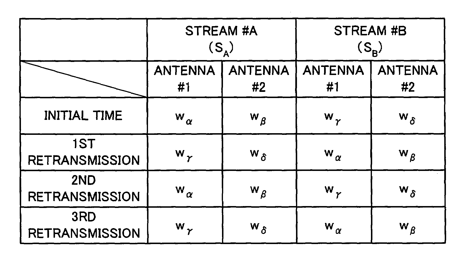
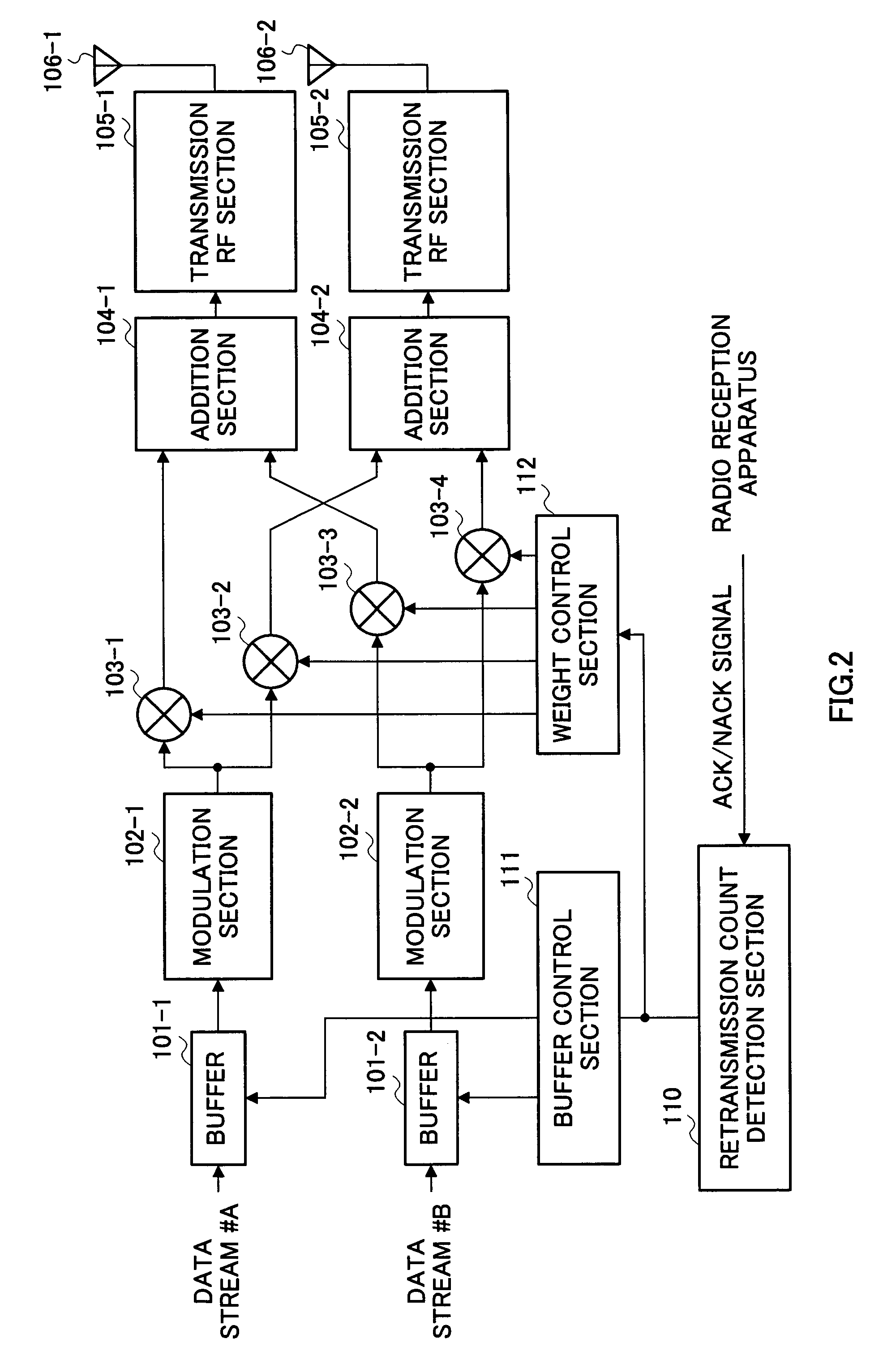
[0036]FIG. 2 is a block diagram showing a configuration of a radio transmission apparatus according to Embodiment 1 of the present invention. Here, a case where two streams; data stream #A and data stream #B are transmitted using two antennas will be explained as an example.

[0037]The radio transmission apparatus shown in FIG. 2 is provided with buffers 101, modulation sections 102, multipliers 103, addition sections 104, transmission radio (RF) sections 105, transmission antennas 106, a retransmission count detection section 110, a buffer control section 111 and a weight control section 112.

[0038]In FIG. 2, the data stream #A is input to the buffer 101-1 and the data stream #B is input to the buffer 101-2.

[0039]The buffers 101-1 and 101-2 store the input data streams in preparation for a data retransmission request from a radio reception apparatus. Then, upon reception of an instruction for data transmission from the buffer control section 111, the buffers 101-1 and 101-2 output the...

embodiment 2

[0086]FIG. 9 is a block diagram showing a configuration of a radio transmission apparatus according to Embodiment 2 of the present invention. This radio transmission apparatus has the same basic configuration as that of the radio transmission apparatus shown in FIG. 2 and the same components are assigned the same reference numerals and explanations thereof will be omitted.

[0087]Features of this embodiment include that it is provided with IFFT sections 201, delay sections 202 and a delay control section 203, it carries out a communication based on an OFDM scheme, adds delay times which differ from one transmission data stream to another, transmits the data streams through their respective antennas at different transmission timings at the time of transmission and thereby drastically changes the characteristic of a received signal on the frequency axis. Therefore, it is possible to drastically change the propagation path environment every time retransmission is performed. Furthermore, ...


PUM


Abstract

Data streams stored in buffers (101) are modulated by modulation sections (102). Multipliers (103) multiply the signals output from the modulation sections (102) by weights output from a weight control section (112). The signals output from the multipliers (103) are added up by addition sections (104), subjected to radio transmission processing by transmission radio sections (105) and sent through antennas (106). A buffer control section (111) controls the buffers (101) based on a retransmission count output from a retransmission count detection section (110). The weight control section (112) outputs weights different from weights at the time of previous transmission to the multipliers (103) every time data is retransmitted. This allows a diversity gain at the time of data retransmission to be increased even if a time variation of the propagation path environment for radio signals is slow.

Description

TECHNICAL FIELD[0001]The present invention relates to a radio transmission apparatus and radio transmission method.BACKGROUND ART[0002]As a technology for realizing communications of large-volume data such as images, MIMO (Multi-Input Multi-Output) communications are being studied actively in recent years.[0003]Among them, BLAST (Bell Laboratories Layered Space-Time) in particular is a focus of attention as an application capable of realizing high-speed transmission using an MIMO channel. This is a technique for transmitting mutually independent (or coded) streams from a plurality of transmission antennas and detecting the respective streams while repeating spatial filtering and removal of replicas on the receiving side.[0004]Furthermore, when the MIMO channel information is known to the transmitting side, it is known that a greater channel capacity can be obtained. More specifically, this is realized by carrying out directivity control using an eigen vector obtained through singula...

Claims


Application Information

Patent Timeline
Patent Type & Authority Patents(United States)
IPC IPC(8): H04J3/16H04J99/00H04B7/04H04B7/06H04B7/08H04B7/10H04B7/26H04J11/00H04L1/00H04L1/06H04L1/18
CPCH04B7/0413H04B7/0613H04B7/0667H04B7/0671H04B7/0417H04B7/0842H04L1/0006H04L1/0015H04L1/0618H04L1/1893H04B7/0697H04B7/0632H04B7/0673H04L1/0026H04B7/04H04L1/1657H04L1/1812
Inventor MIYOSHI, KENICHI
Owner INTERDIGITAL PATENT HLDG INC
Why Eureka
Try Eureka