Method for checking printability of a lithography target
a lithography target and printability technology, applied in the field of integrated circuit fabrication, can solve the problems of increasing the chip size and the process can waste precious design tim
- Summary
- Abstract
- Description
- Claims
- Application Information
AI Technical Summary
Benefits of technology
Problems solved by technology
Method used
Image
Examples
Embodiment Construction
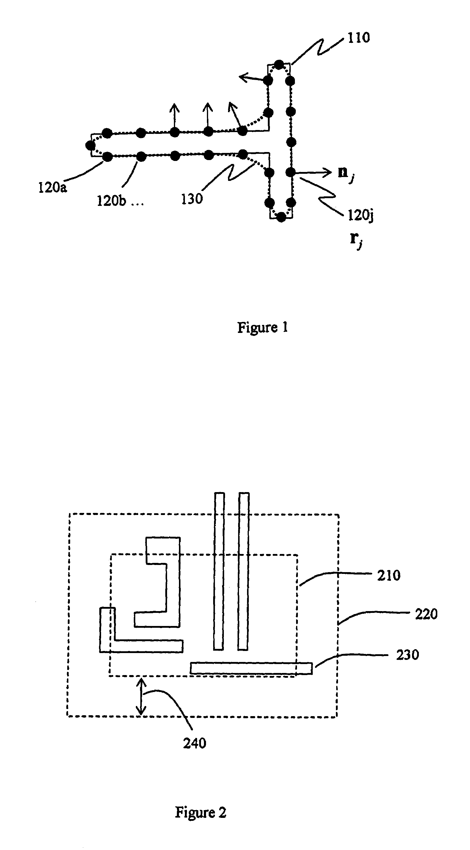
[0025]The terms “karo”, “target points,” and “normal vectors” are used in the description, and will first be defined.
[0026]Techniques hereof check a small region of the target layer at a time. This region is called a karo. The union of karos cover the chip, or the part of the layout to be checked. Karos may overlap. Karos are rectangular in a preferred embodiment, although in alternative embodiments they can have any shape. The preferred size of a karo is between 0.5 and 2 micrometers for 193 nm exposure wavelength.
[0027]In a given karo, target points r1,r2, . . . , rM are selected on the edges of target polygons. The target points are used to help encapsulate the design requirements by a mathematical expression. In an embodiment hereof, target points on a polygon are approximately equally spaced by a distance of (kSAMPLE λ / NA), where kSAMPLE is a dimensionless factor that is less than 0.25 and preferably larger than 0.1; λ is the exposure wavelength, and NA is the numerical apertur...
PUM
 Abstract
Description
Claims
Application Information
 - R&D
- Intellectual Property
- Life Sciences
- Materials
- Tech Scout
- Unparalleled Data Quality
- Higher Quality Content
- 60% Fewer Hallucinations
Browse by: Latest US Patents, China's latest patents, Technical Efficacy Thesaurus, Application Domain, Technology Topic, Popular Technical Reports.
© 2025 PatSnap. All rights reserved.Legal|Privacy policy|Modern Slavery Act Transparency Statement|Sitemap|About US| Contact US: help@patsnap.com


