Ablation catheter with tissue protecting assembly

a tissue protecting and catheter technology, applied in the field of tissue ablation devices and methods, can solve the problems of difficult to create transmural lesions using current technology, dissipation or loss of rf energy through intervening organs, tissues, blood pools, etc., and achieve the difficulty of ablation tissue below the surface of the target site using current unipolar arrangements

Active Publication Date: 2009-08-04
BOSTON SCI SCIMED INC
View PDF31 Cites 190 Cited by
  • Summary
  • Abstract
  • Description
  • Claims
  • Application Information

AI Technical Summary

Problems solved by technology

Because the ventricle tissue is thick, however, it may be difficult to create transmural lesions using the current technology.
One of the disadvantages of this procedure is that much of the RF energy is dissipated or lost through intervening organs, tissues, and / or blood pool between the ground pad and the target tissue that is being ablated.
As the result, it is more difficult to ablate tissue below the surface of the target site using current unipolar arrangements.
As a result, it is more difficult to ablate tissue below the surface of the target site using current bipolar arrangements.
Another problem associated with current ablation devices is that during an ablation procedure, a return electrode used for returning energy to an ablation source may heat up.
In the unipolar arrangement where the return electrode is placed in contact with a patient's skin, the overheating of the return electrode may cause injury to the patient's skin.
In the bipolar arrangement where the return electrode is placed within the body and adjacent to the ablating electrode, the overheating of the return electrode may cause internal healthy tissue that is in contact with the return electrode to be unnecessarily heated.
Furthermore, ablation of heart tissue poses another challenge in that the heart is constantly moving during an ablation procedure.
As a result, it is difficult to maintain stable contact between an ablating or ground electrode and the constantly moving target tissue.

Method used


Image

  • Ablation catheter with tissue protecting assembly
  • Ablation catheter with tissue protecting assembly
  • Ablation catheter with tissue protecting assembly

Examples


Embodiment Construction

[0054]Various embodiments of the present invention are described hereinafter with reference to the figures. It should be noted that the figures are not drawn to scale and that elements of similar structures or functions are represented by like reference numerals throughout the figures. It should also be noted that the figures are only intended to facilitate the description of specific embodiments of the invention. They are not intended as an exhaustive description of the invention or as a limitation on the scope of the invention. In addition, an illustrated embodiment needs not have all the aspects or advantages of the invention shown. An aspect or an advantage described in conjunction with a particular embodiment of the present invention is not necessarily limited to that embodiment and can be practiced in any other embodiments of the present invention even if not so illustrated.

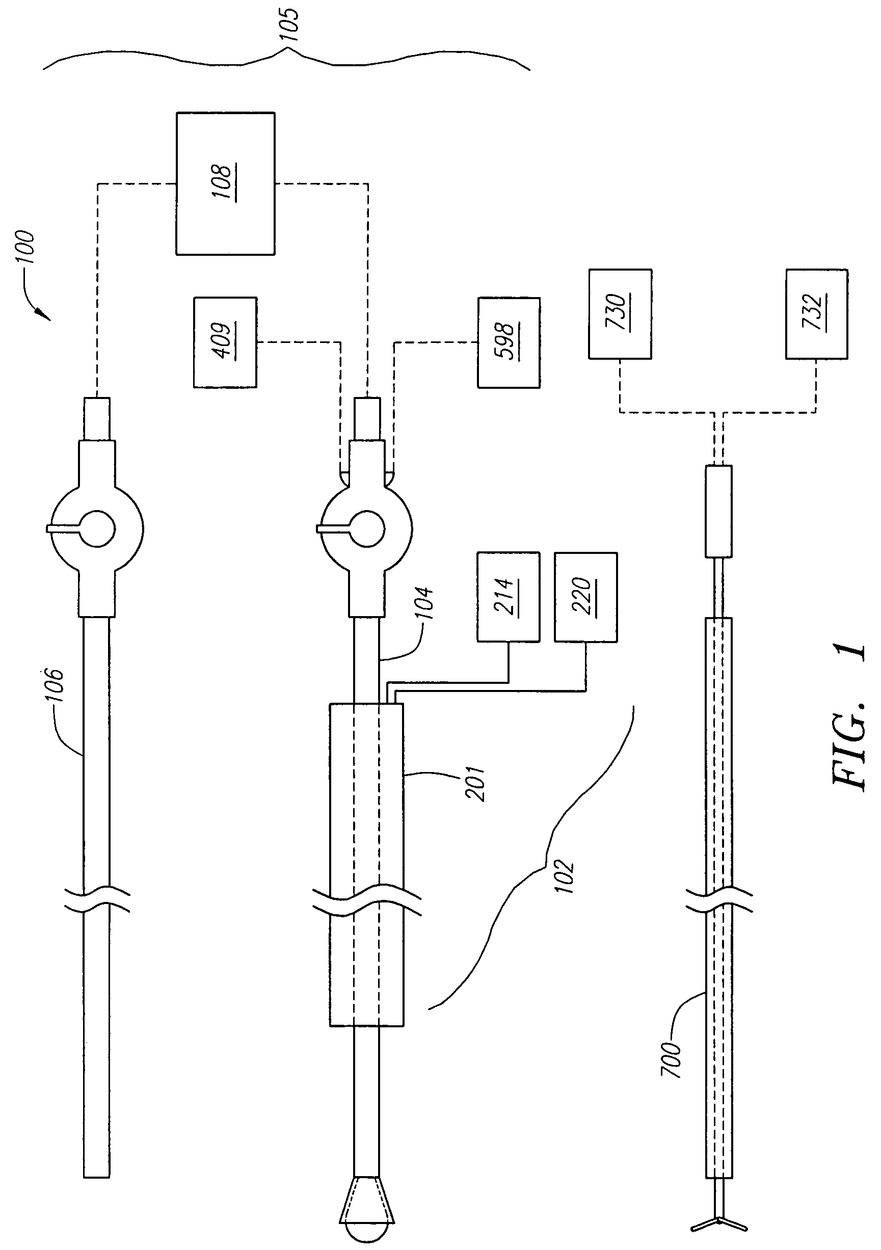
[0055]Referring to FIG. 1, a tissue ablation system 100 constructed in accordance with one embodiment of...


PUM


Abstract

A medical probe includes an elongate member having a proximal end and a distal end, an ablative element mounted to the distal end of the elongate member, and a cage assembly mounted to the distal end of the elongate member, the cage assembly at least partially covers the ablative element. A method of treating tissue in a body includes inserting an ablative element in the body, placing the ablative element adjacent the tissue, and maintaining a distance between the ablative element and the tissue using a protective catheter element that circumscribes at least a portion of the ablative element.

Description

FIELD OF THE INVENTION[0001]The present invention pertains to devices and methods for ablation of tissue, and more particularly, to ablation devices and methods for creating lesions within internal body organs, such as the heart.BACKGROUND[0002]Physicians make use of catheters today in medical procedures to gain access into interior regions of the body to ablate targeted tissue areas. For example, in electrophysiological therapy, ablation is used to treat cardiac rhythm disturbances. During these procedures, a physician steers a catheter through a main vein or artery into the interior region of the heart that is to be treated. The physician places an ablating element carried on the catheter near the targeted cardiac tissue, and directs energy from the ablating element to ablate the tissue and form a lesion. Such procedure may be used to treat arrhythmia, a condition in the heart in which abnormal electrical signals are generated in the heart tissue.[0003]In certain procedures, it ma...

Claims


Application Information

Patent Timeline
Patent Type & Authority Patents(United States)
IPC IPC(8): A61B18/18A61B18/14A61B19/00
CPCA61B18/1492A61B18/082A61B5/042A61B2018/00065A61B2018/00214A61B2018/00238A61B2018/1472A61B2019/4036A61B2018/00351A61B2090/0436A61B5/283
Inventor PHAN, HUYSWANSON, DAVID
Owner BOSTON SCI SCIMED INC
Why Eureka
Try Eureka