Magnetic resonance imaging apparatus and method

a magnetic resonance imaging and apparatus technology, applied in the direction of instruments, magnetic measurements, measurement devices, etc., can solve the problems of large changes in the position of the target section, the length of the required imaging time, and the inability to utilize all the collected data for reconstruction

Inactive Publication Date: 2009-08-04
TOSHIBA MEDICAL SYST CORP
View PDF8 Cites 54 Cited by
  • Summary
  • Abstract
  • Description
  • Claims
  • Application Information

AI Technical Summary

Problems solved by technology

However, when the movement compensation method is employed, not all data collected can be utilized for reconstruction, and the required imaging time is lengthened.
In this case, the position of a target section is greatly changed, and may fall outside an allowable area for a long time.
This further reduces the probability of employment of collected data for reconstruction, which further lengthens the required imaging period.
At worst, the target section may always fall outside the allowable area.
In this case, reconstruction cannot be realized, and hence the imaging operation cannot be finished.
In the above-described movement compensation method, however, the slicing position is moved in the static magnetic field during imaging, which means that the slicing position cannot be kept at a position at which the static magnetic field is uniform.
Accordingly, if the imaging method sensitive to static magnetic field uniformity is combined with the above-mentioned movement compensation method, the degree of suppression of the occurrence of fat tissue signals may be reduced, and a reduction in image quality, such as an increase in banding artifacts in the SSFP method, may be involved.

Method used


Image

  • Magnetic resonance imaging apparatus and method
  • Magnetic resonance imaging apparatus and method
  • Magnetic resonance imaging apparatus and method

Examples


Embodiment Construction

[0031]An embodiment will be described with reference to the accompanying drawings.

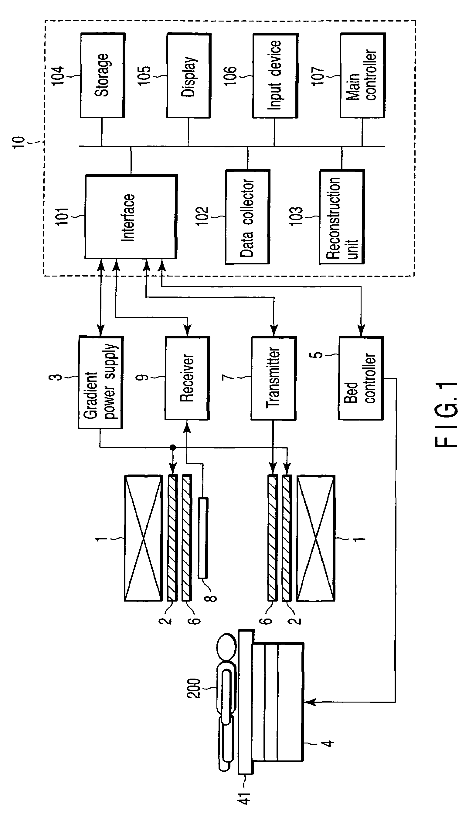
[0032]FIG. 1 shows an MRI apparatus according to the embodiment. As shown, the MRI apparatus comprises a static field magnet 1, gradient coil 2, gradient power supply 3, bed 4, bed controller 5, transmission RF coil 6, transmitter 7, receiving RF coil 8, receiver 9 and computer system 10.

[0033]The static field magnet 1 is a hollow cylinder and generates a uniform static magnetic field in its internal space. The static field magnet 1 is formed of, for example, a permanent magnet or superconductive magnet.

[0034]The gradient coil 2 is also a hollow cylinder and is provided inside the static field magnet 1. The gradient coil 2 is formed of three coils perpendicular to each other and corresponding to the X-, Y- and Z-axes. In the gradient coil 2, the three coils are supplied with a current from the gradient power supply 3 to generate gradient magnetic fields having their respective magnetic field intensitie...


PUM


Abstract

A magnetic resonance imaging apparatus includes a movement unit which moves a subject placed in a static magnetic field, a collector which collects data corresponding to a magnetic resonance signal emitted from the subject, a detector which detects a position of a particular section of the subject in the static magnetic field, a reconstruction unit which reconstructs an image, based on the collected data, when the detected position falls within an allowable area, and a controller which controls the movement unit to compensate for a deviation of the detected position from a reference position.

Description

CROSS-REFERENCE TO RELATED APPLICATIONS[0001]This application is based upon and claims the benefit of priority from prior Japanese Patent Application No. 2006-004019, filed Jan. 11, 2006, the entire contents of which are incorporated herein by reference.BACKGROUND OF THE INVENTION[0002]1. Field of the Invention[0003]The present invention relates to a magnetic resonance imaging (MRI) apparatus and method for performing image reconstruction, using data collected when a body portion, such as the diaphragm, is positioned in a preset allowable area.[0004]2. Description of the Related Art[0005]The heart, for example, moves in accordance with, for example, breathing. As an imaging method employed to perform imaging of such a moving target section, there is a known movement compensation method in which data collected when the target section is positioned within a preset allowable area is utilized for reconstructing the target section. In the movement compensation method, a magnetic resonanc...

Claims


Application Information

Patent Timeline
Patent Type & Authority Patents(United States)
IPC IPC(8): G01V3/00
CPCG01R33/56375G01R33/56383
Inventor SUGIURA, SATOSHI
Owner TOSHIBA MEDICAL SYST CORP
Why Eureka
Try Eureka