Thermo-optic liquid crystal waveguides

a liquid crystal waveguide and optical technology, applied in static indicating devices, instruments, non-linear optics, etc., can solve the problems of difficult to compact such mechanical devices, undesirable mechanical control of light, and limited lifetime of mechanically moving devices

Active Publication Date: 2009-08-04
ANALOG DEVICES INC
View PDF46 Cites 48 Cited by
  • Summary
  • Abstract
  • Description
  • Claims
  • Application Information

AI Technical Summary

Benefits of technology

[0008]In light of the above and according to one broad aspect of one embodiment of the present invention, disclosed herein is a waveguide having an adjustable index of refraction (or an adjustable optical path length, or an adjustable optical phase delay). In one example, the waveguide includes a core for guiding a light beam through the waveguide; at least one cladding; liquid crystal material disposed within the waveguide; and at least one temperature control element for receiving at least one control signal to control a temperature of at least a portion of the liquid crystal material; wherein the index of refraction (or the optical path length, or the optical phase delay) of the waveguide is altered by an amount that is controlled by the control signal.
[0009]In one example, the liquid crystal material may be disposed within the at least one cladding, and the liquid crystal material may be a nemetic material. The at least one temperature control element may include a resistive heater and / or may include at least one conductive layer.
[0010]In another example, the at least one temperature control element includes an upper temperature control element and a lower temperature control element.
[0011]The light beam traveling in the waveguide may include TM polarized light and / or TE polarized light. The at least one control signal may include a DC voltage, an AC voltage, a current (DC or AC), or any other electrical signal depending upon the implementation.

Problems solved by technology

However, mechanical control over light is undesirable for several reasons.
First, it is difficult to make such mechanical devices compact.
Second, the mechanical nature of such moving devices have limited lifetimes due to mechanical wear and failure issues.
Third, mechanical devices are inherently vibration sensitive, which limits the type of environment in which they can be used.
Finally, mechanical devices necessitate a level of design complexity including gears, bearings, and other mechanical components, which add cost, expense, and maintenance issues to such designs.
These devices are therefore typically power consumptive, which is prohibitive for many applications.

Method used


Image

  • Thermo-optic liquid crystal waveguides
  • Thermo-optic liquid crystal waveguides
  • Thermo-optic liquid crystal waveguides

Examples


Embodiment Construction

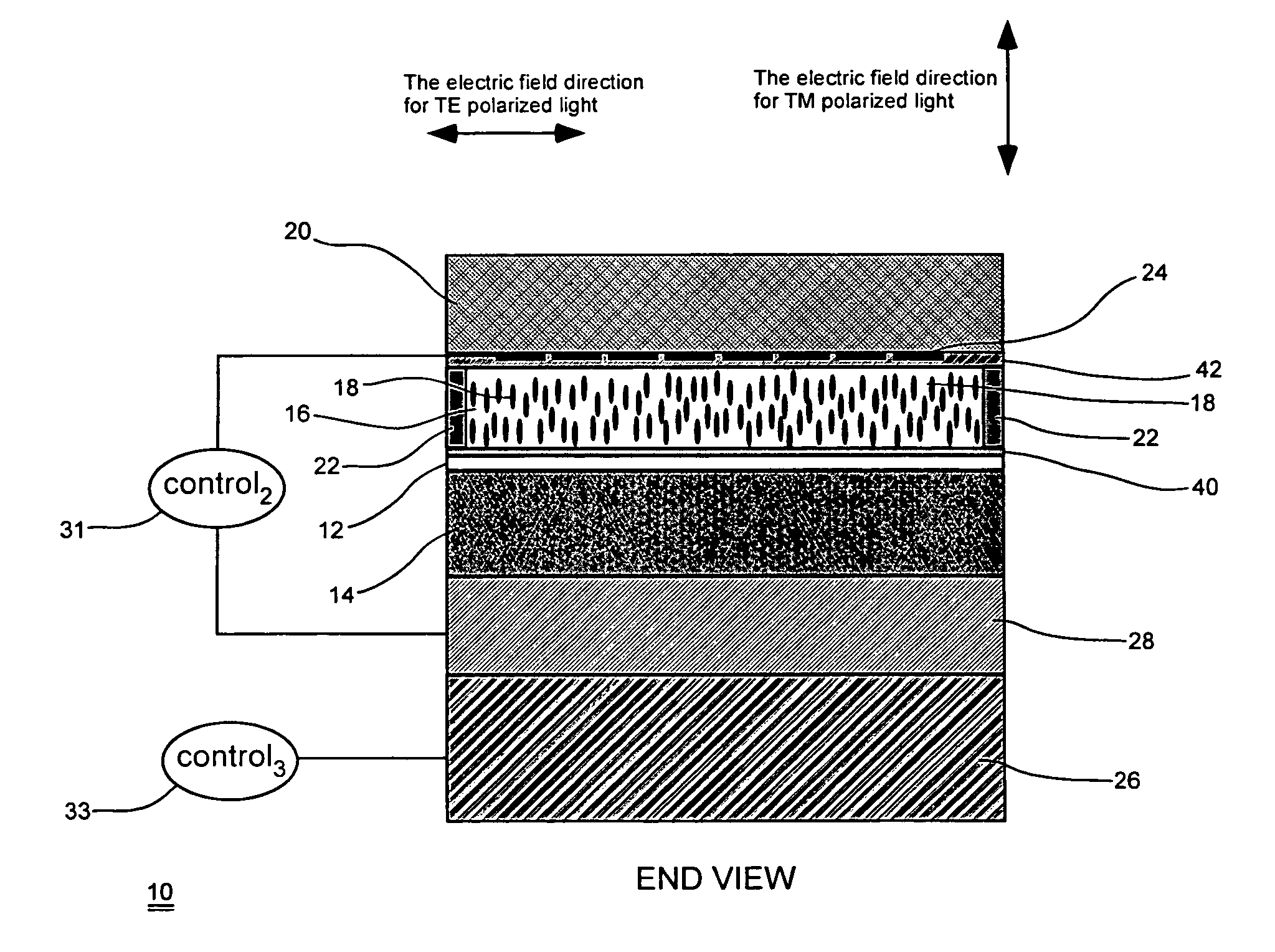
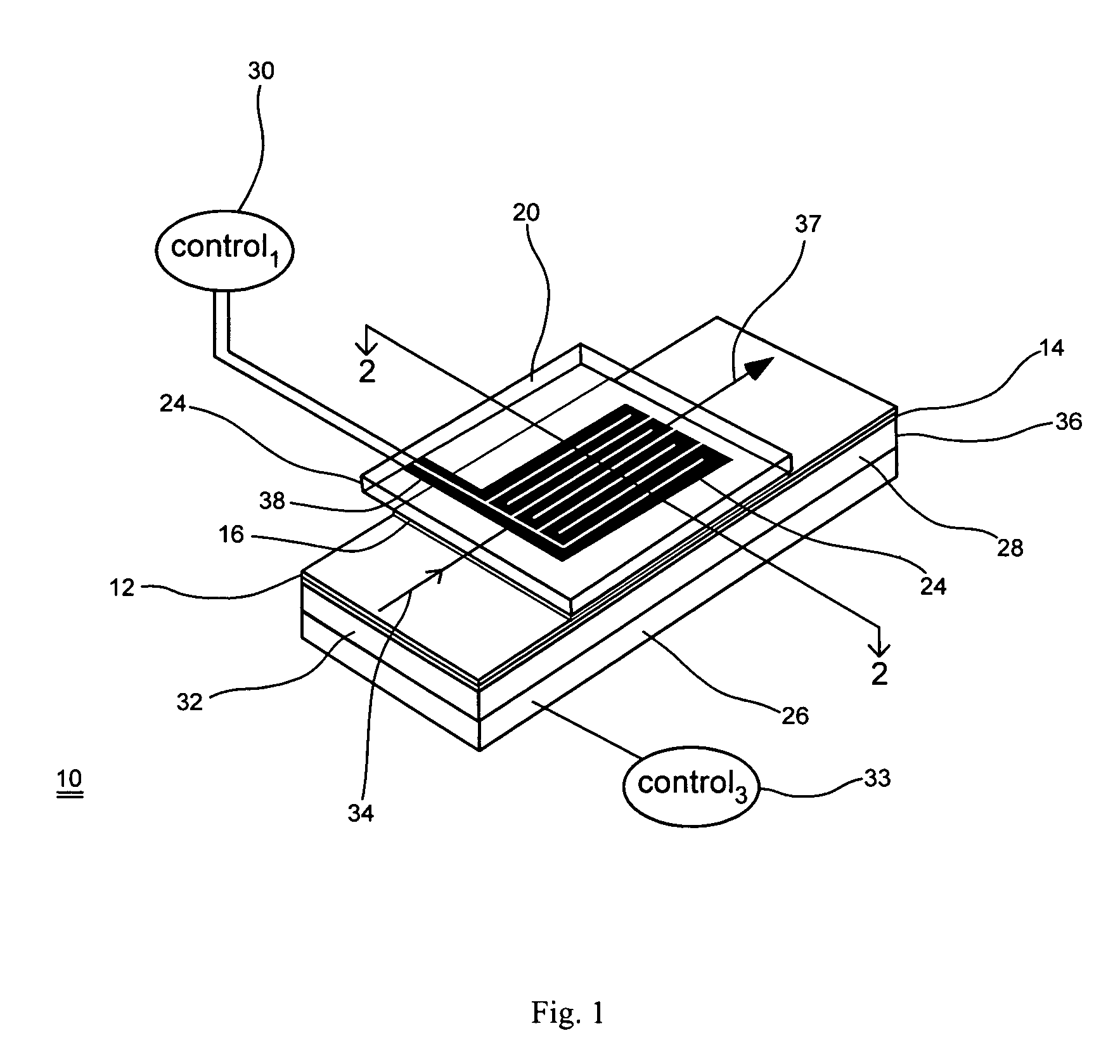
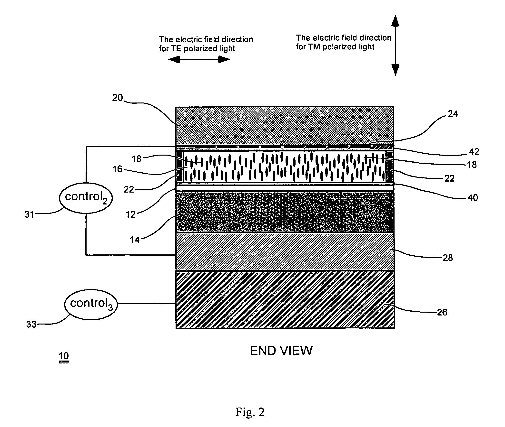
[0015]Disclosed herein are various embodiments of a liquid crystal waveguide for dynamically controlling the index of refraction (or optical path length) of the waveguide, and thereby controlling the propagation speed of light passing through the waveguide. This thereby enables control of the amount of optical phase delay (OPD) of light passing through the waveguide. Generally, liquid crystal materials can be disposed within a waveguide in a cladding proximate or adjacent to a core layer of the waveguide, however liquid crystal material may be included in all or part of the waveguide core. According to some embodiments of the present invention, the temperature of the liquid crystal material can be controllably altered, thereby altering the index of refraction of the waveguide for light traveling through the waveguide.

[0016]Liquid crystals may have indices of refraction that depend on temperature to a much larger extent than more conventional materials such as silicon dioxide (SiO2) ...


PUM

PropertyMeasurementUnit
temperatureaaaaaaaaaa

Abstract

A waveguide having an adjustable index of refraction (or an adjustable optical path length, or for providing an adjustable optical phase delay) based in part on thermal effects in the waveguide. In one example, the waveguide may include a core for guiding a light beam through the waveguide; at least one cladding; liquid crystal material disposed within the waveguide; and at least one temperature control element, such as resistive heater, for receiving at least one control signal to control a temperature of at least a portion of the liquid crystal material; wherein the index of refraction (or the optical path length, or the optical phase delay of the light beam) of the waveguide is altered by an amount that is controlled by the control signal.

Description

CROSS-REFERENCE TO RELATED APPLICATIONS[0001]This application claims under 35 U.S.C. § 119(e) the benefit of U.S. provisional patent application No. 60 / 713,393 entitled “Thermo-optic Liquid Crystal Waveguides,” filed Sep. 1, 2005, the disclosure of which is hereby incorporated by reference in its entirety.[0002]This application also incorporates by reference U.S. patent application Ser. No. 11 / 040,549, filed Jan. 21, 2005, entitled “Tunable Laser Having Liquid Crystal Waveguide,” and U.S. patent application Ser. No. 10 / 963,946, filed Oct. 12, 2004, entitled “Liquid Crystal Waveguide Having Refractive Shapes for Dynamically Controlling Light,” the disclosures of which are hereby incorporated by reference in their entirety.BACKGROUND OF THE INVENTION[0003]Light can be controlled using standard lenses and mirrors. These passive methods can be made active via mechanical motion. For example, mirrors can be placed on motorized stages or piezo mounts to move the mirror to control either th...

Claims


Application Information

Patent Timeline
Patent Type & Authority Patents(United States)
IPC IPC(8): G02F1/133G02F1/295
CPCG02F1/1326G02F1/132G02F1/313
Inventor ANDERSON, MICHAEL H.ROMMEL, SCOTT D.DAVIS, SCOTT R.
Owner ANALOG DEVICES INC
Why Eureka
Try Eureka