System and method of communicating signals

a communication system and signal technology, applied in the field of wireless communication, can solve the problems of limiting system performance, system performance may experience degradation, and temporary increases in the ber of demodulated information

Inactive Publication Date: 2009-08-11
GENERAL ELECTRIC CO
View PDF4 Cites 30 Cited by
  • Summary
  • Abstract
  • Description
  • Claims
  • Application Information

AI Technical Summary

Benefits of technology

[0014]In accordance with yet another aspect of the present technique, a method of communicating signals is presented. The method includes receiving a digital signal having a remodulated signal spectrum of a signal transmitted via one or more transmitters. In addition, the method includes extracting individual copies of the transmitted signal. The method also includes translating each of the individual copies to baseband via a numerically controlled oscillator and a mixer. Further, the method includes reducing sampling frequency of each of the individual copies via one or more stages of decimation filtering. Additionally, the method includes resampling each of the individual copies to align each of the individual copies in time. The method also includes combining the time-aligned copies. Further, the method includes processing the combined time-aligned copies via a detector to generate a single digital output signal.

Problems solved by technology

Furthermore, wireless communication systems often operate in environments with severe fading due to multi-path propagation, which limits system performance.
When using such “selection combining”, the system performance may experience degradation due to loss of data experienced during antenna switching.
Additionally, if the rate at which the antennas are switched is not high enough, changes in the environment may not be adequately tracked, resulting in temporary increases in the BER of the demodulated information.

Method used


Image

  • System and method of communicating signals
  • System and method of communicating signals
  • System and method of communicating signals

Examples


Embodiment Construction

[0027]Wireless communication systems are being increasingly employed in various fields. Further, wireless communication systems suffer from degradation of system performance as they often operate in environments with severe fading due to multi-path propagation. Multiple-antenna systems have been used to mitigate the problem of fading. In addition, spatial diversity schemes have been employed to enhance performance of wireless communication systems. However, the wireless communication systems using spatial diversity suffer from degradation of performance due to increased switching time between antennas, loss of data during antenna switching and higher BER. It may therefore be desirable to develop a robust technique that advantageously facilitates enhanced performance of the wireless communication systems. The techniques discussed herein address some or all of these issues.

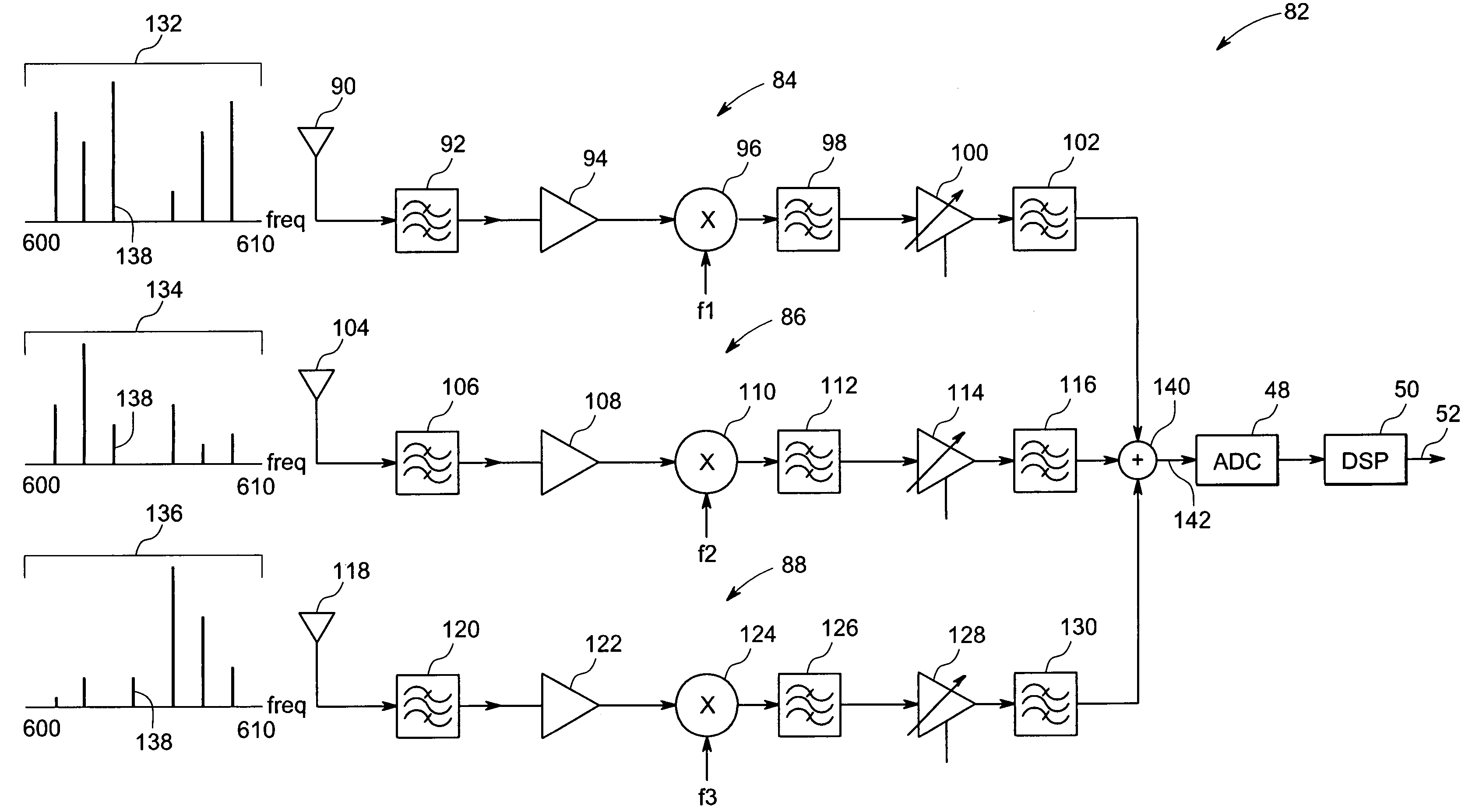
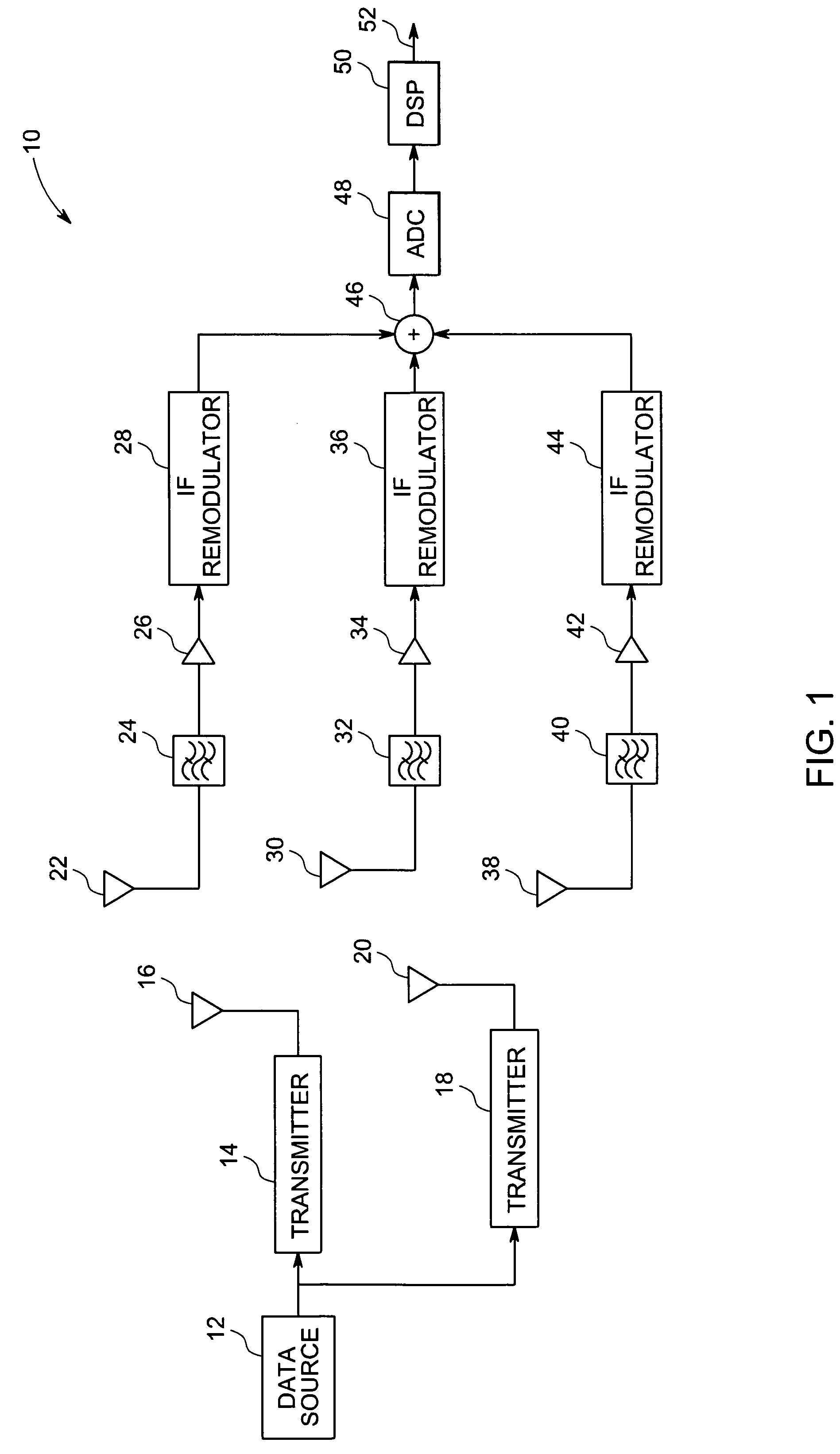
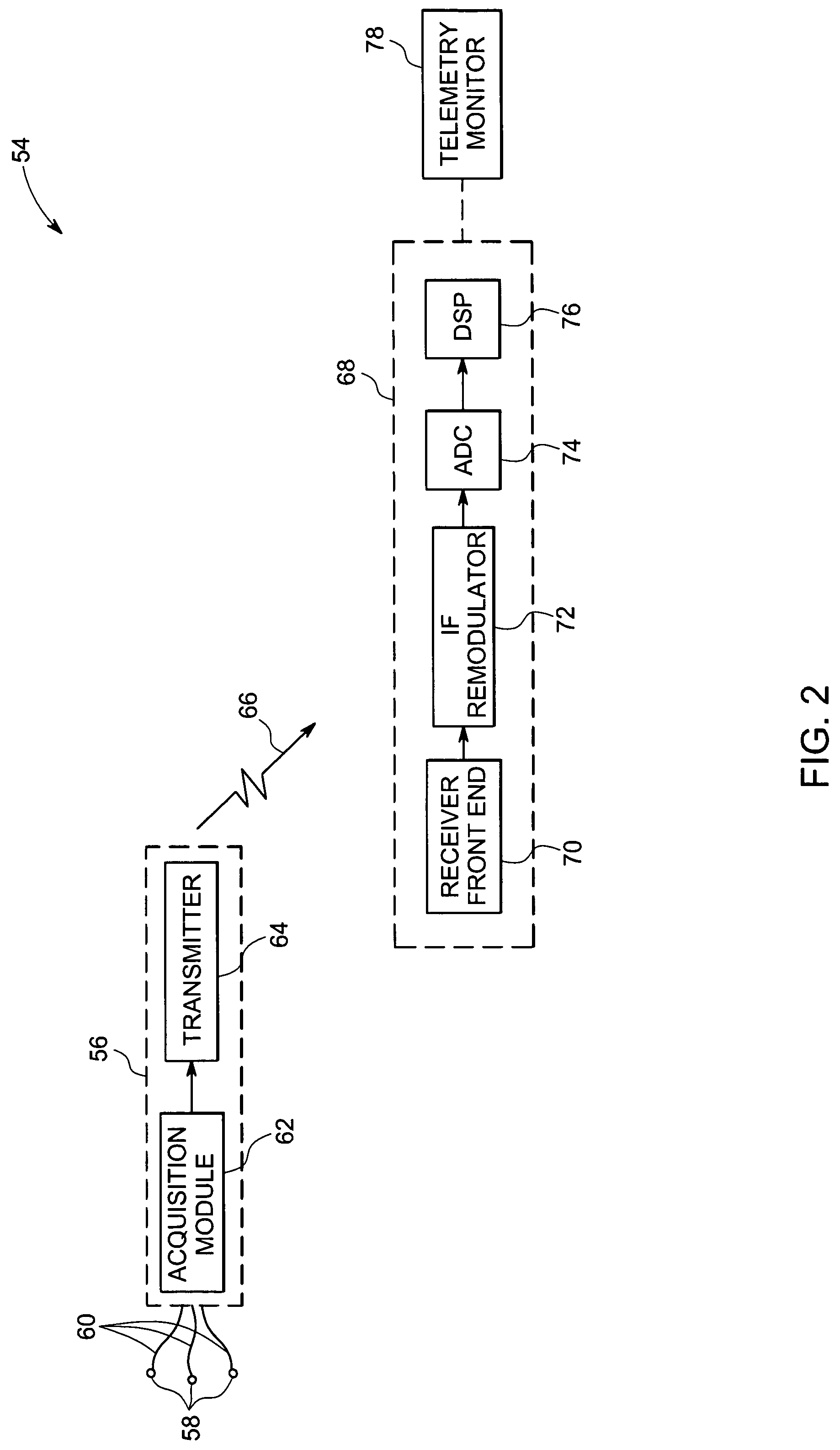
[0028]Referring to FIG. 1, an exemplary wireless communication system 10, in accordance with aspects of the prese...


PUM

PropertyMeasurementUnit
frequencyaaaaaaaaaa
frequencyaaaaaaaaaa
frequencyaaaaaaaaaa

Abstract

A communication system is presented. The system includes one or more transmitters configured to transmit a signal, where each of the signals generated by the one or more transmitters corresponds to a respective frequency. Further, the system includes a plurality of receiver front-ends configured to receive the signal transmitted by each of the one or more transmitters. The system also includes a plurality of remodulator modules configured to translate each of the received signals to a signal having a respective intermediate frequency. In addition, the system includes a combining module configured to combine each of the signals having respective intermediate frequencies to generate a single composite signal. Also, the system includes a single analog-to-digital converter configured to process the composite signal and generate a digital output. Additionally, the system includes a digital signal processor module configured to extract the signal transmitted by each of the one or more transmitters.

Description

BACKGROUND[0001]The invention relates generally to wireless communication, and more particularly to wireless transmission of data from mobile data acquisition units to a stationary central receiver.[0002]Wireless services are increasingly ubiquitous and useful components in the global communication infrastructure, and wireless data telemetry is widely used because it allows collection of sensor information from any location in an antenna coverage area without reconfiguration of the communications infrastructure. An example of particular importance in medical practice is the wireless transmission of the electrocardiogram (ECG) data and other physiological monitoring signals acquired from patients in a hospital environment. Wireless telemetry allows these patients to be mobile, while vital signs of the patients are continuously monitored.[0003]Many wireless telemetry systems are structured to employ frequency division multiple access (FDMA) schemes. In an FDMA transmission, each trans...

Claims


Application Information

Patent Timeline
Patent Type & Authority Patents(United States)
IPC IPC(8): G01K5/00
CPCH04B7/0857A61B5/0006
Inventor HOCTOR, RALPH THOMASZINSER, JR., RICHARD LOUISGRUBIS, MATTHEW GEORGESEIDL, NEAL JOHN
Owner GENERAL ELECTRIC CO
Why Eureka
Try Eureka