Compact Raman or fluorescence excitation system

a fluorescence excitation and compact technology, applied in the field of compact, handheld spectroscopic units, can solve the problems of misalignment or improper focusing of incident illumination from laser diodes, and it is harder to establish a compact geometry for the system, and achieve the effect of simplifying the system configuration

Active Publication Date: 2009-08-11
CHEMIMAGE TECH LLC
View PDF11 Cites 12 Cited by
  • Summary
  • Abstract
  • Description
  • Claims
  • Application Information

AI Technical Summary

Benefits of technology

[0011]In one embodiment, the present disclosure relates to a compact Raman and fluorescence spectroscopy system that uses a microprism or micromirror based optical structure to accomplish the introduction of excitation radiation with compactness and simplified system configuration for portable or mobile spectroscopy applications. A microprism may be glued to a surface location of a focusing lens in the system to directly receive the illumination signal without intervening optical components. In one embodiment, the microprism may be simply placed in close physical proximity to the focusing lens without being glued thereto. On the other hand, a micromirror may be used instead of a microprism. The illuminating photons received by the microprism or micromirror may be directly transferred to the sample under investigation via the focusing lens. The compact system may be made portable and may further include an on-board spectrometer with or without a display unit. For chemical detecting applications, a detector (e.g., a CCD detector) may also be provided along with the spectrometer.

Problems solved by technology

Because of the 6.5° tilt (from the vertical) of the longpass filter 16, an improper separation between the focusing lens 18 and the longpass filter 16 may result in misalignment or improper focusing of the incident illumination from the laser diode 12.
Also, the more the number of system components in the system 10, the harder it becomes to establish a compact geometry for the system 10 because of the constraints placed by components' physical dimensions and the minimum separation required between various components for accurate optical measurements.

Method used


Image

  • Compact Raman or fluorescence excitation system
  • Compact Raman or fluorescence excitation system
  • Compact Raman or fluorescence excitation system

Examples


Embodiment Construction

[0022]The accompanying figures and the description that follows set forth the present disclosure in embodiments of the present disclosure. However, it is contemplated that persons generally familiar with optics, operation and maintenance of optical instruments (including spectroscopic instruments), or optical spectroscopy will be able to apply the teachings of the present disclosure in other contexts by modification of certain details. Accordingly, the figures and description are not to be taken as restrictive of the scope of the present disclosure, but are to be understood as broad and general teachings. In the discussion herein, when any numerical range of values is referred or suggested, such range is understood to include each and every member and / or fraction between the stated range of minimum and maximum.

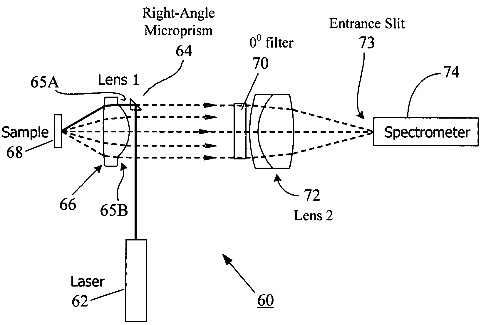
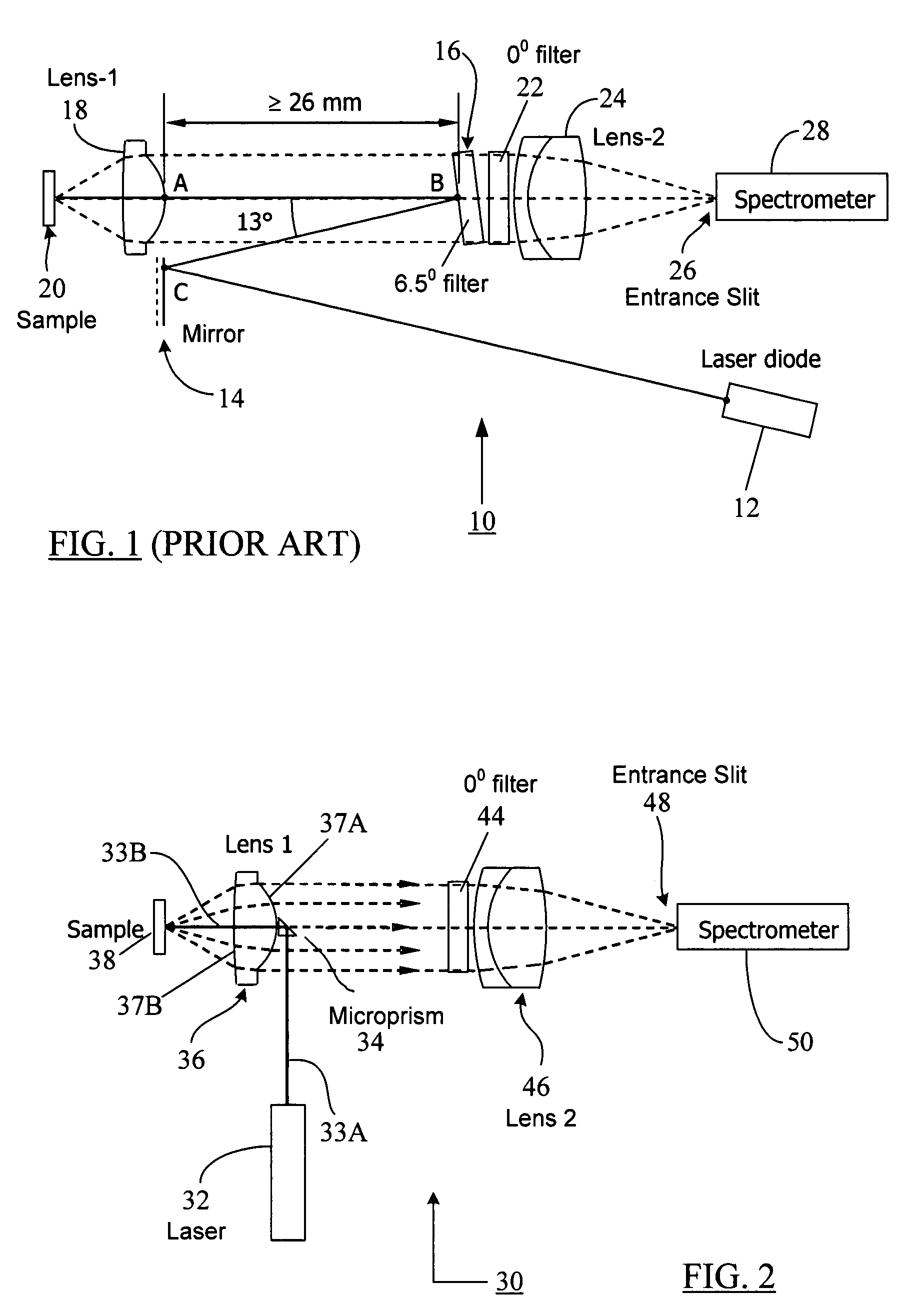
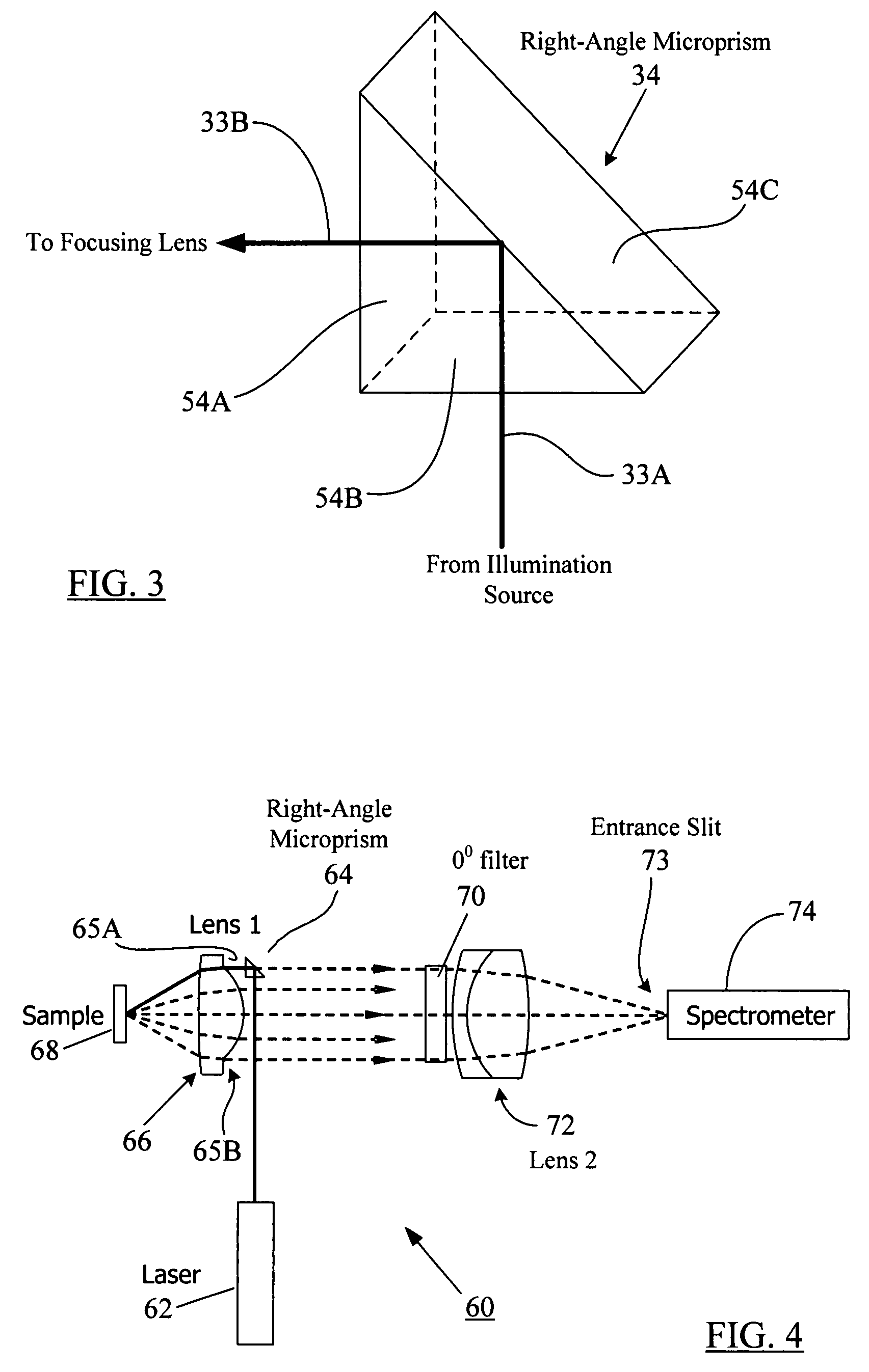
[0023]FIG. 2 depicts an exemplary microprism-based compact and portable Raman or fluorescence spectroscopy system 30 according to one embodiment of the present disclosure. In ...


PUM

PropertyMeasurementUnit
angle of incidenceaaaaaaaaaa
wavelengthsaaaaaaaaaa

Abstract

A compact Raman and fluorescence spectroscopy system that uses a microprism or micromirror based optical structure to accomplish the introduction of excitation radiation with compactness and simplified system configuration for portable or mobile spectroscopy applications. A microprism may be glued to a surface location of a focusing lens in the system to directly receive the illumination signal without intervening optical components. Alternatively, the microprism may be simply placed in close physical proximity of the focusing lens without being glued thereto. On the other hand, a micromirror may be used instead of the microprism. The illuminating photons received by the microprism or micromirror may be directly transferred to the sample under investigation via the focusing lens. The compact system may be made portable and may further include an on-board spectrometer with or without a display unit. For chemical detecting applications, a detector (e.g., a CCD array) may also be provided along with the spectrometer.

Description

REFERENCE TO RELATED APPLICATION[0001]The disclosure in the present application claims priority benefit under 35 U.S.C. § 119(e) of the U.S. Provisional Application No. 60 / 839,065, titled “Compact Spectroscopy System,” and filed on Aug. 21, 2006, the disclosure of which is incorporated herein by reference in its entirety.BACKGROUNDField of the Disclosure[0002]The present disclosure generally relates to spectroscopy systems and, more particularly, to a compact, hand-held spectroscopic unit for in-field Raman, fluorescence, or other chemical detection applications.BRIEF DESCRIPTION OF RELATED ART[0003]Some modern spectroscopy applications require handheld or portable spectroscopy systems that can be employed in the field and can be easily transported from one testing location to another. For example, a law enforcement department may need a mobile spectroscopy unit that can be easily carried to a threat location (e.g., a location where an anthrax threat may be present) for on-the-spot ...

Claims


Application Information

Patent Timeline
Patent Type & Authority Patents(United States)
IPC IPC(8): G01J3/02G01J3/44G01N21/64G01N21/65
CPCG01J3/02G01J3/021G01J3/0272G01J3/44G01J3/0256G01N2201/0221
Inventor ZHANG, JINGYUN
Owner CHEMIMAGE TECH LLC
Why Eureka
Try Eureka