Photoelectric ion source photocathode regeneration system

a photocathode and photoelectric ion technology, applied in the direction of instruments, particle separator tube details, separation processes, etc., can solve the problems of difficult removal, inconvenient or expensive surface rubbing by human operators, sampling orifice contamination with vapor-emitting particles, etc., and achieve the effect of raising the temperature of the photocathod

Active Publication Date: 2009-08-18
LEIDOS SECURITY DETECTION & AUTOMATION INC
View PDF1 Cites 14 Cited by
  • Summary
  • Abstract
  • Description
  • Claims
  • Application Information

AI Technical Summary

Benefits of technology

[0025]The maximum temperature may be set to be sufficient to remove any accumulated coating or oxidation on the photocathode. The total Joules expended to heat the photocathode may be minimized to conserve energy in a battery-operated instrument, and thus as much thermal insulation as is possible may be employed. Additionally, the mass of photocathode, any substrate, and the heater assembly may be minimized to permit rapid thermal cycling and energy conservation. It may not be a requirement to completely regenerate the photocathode to a pristine, original state. Some photocathode materials rapidly degrade in the rate of electron emission upon exposure to clean air when irradiated with UV photons, but this degradation may reach a limit of about 30% to 50% of the maximum emission after several minutes of operation. This “burned in” emission rate may be more stable than the pristine emission rate and may be more useful for use in an analytical instrument. Thus, it may not be necessary to regenerate the photocathode all the way to a pristine state, thus saving energy and causing less morphological degradation of the photocathode.

Problems solved by technology

Examples may include, but not be limited to, sampling of vapor from complex surfaces that contain many holes, crevices, or deep depressions, textured materials such as cloth, people and animals that prefer not to be rubbed by absorbent material, large three dimensional objects, surfaces that must be sampled in a short time, and surfaces in which surface rubbing by human operators is inconvenient or expensive.
In addition, it has been observed that the sampling orifice may become contaminated with vapor-emitting particles if the sample inadvertently contacts the orifice.
Such contamination is particularly difficult to remove in a short period of time, thus preventing continuous operation of the instrument.
This can be particularly severe for an IMS, where the photocathode is operated at atmospheric pressure, rather than a vacuum.

Method used


Image

  • Photoelectric ion source photocathode regeneration system
  • Photoelectric ion source photocathode regeneration system
  • Photoelectric ion source photocathode regeneration system

Examples


Embodiment Construction

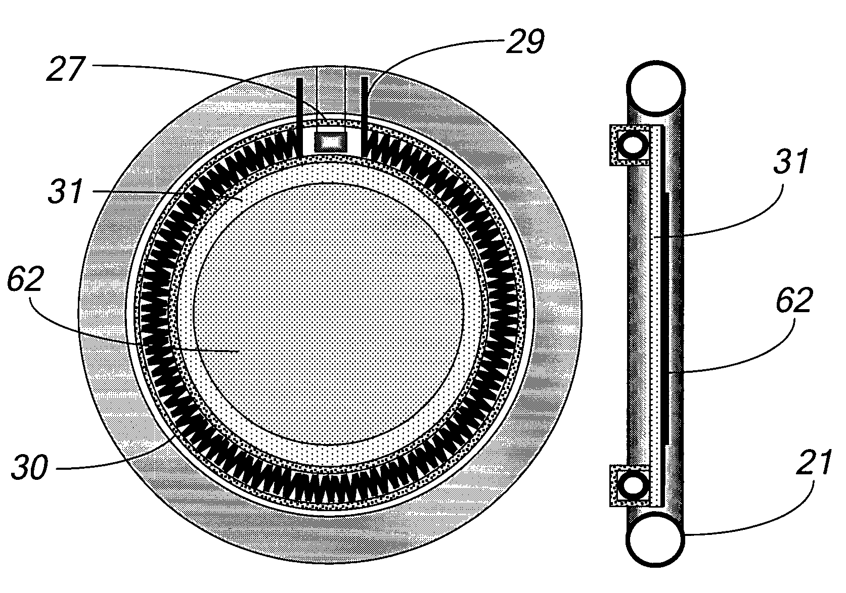
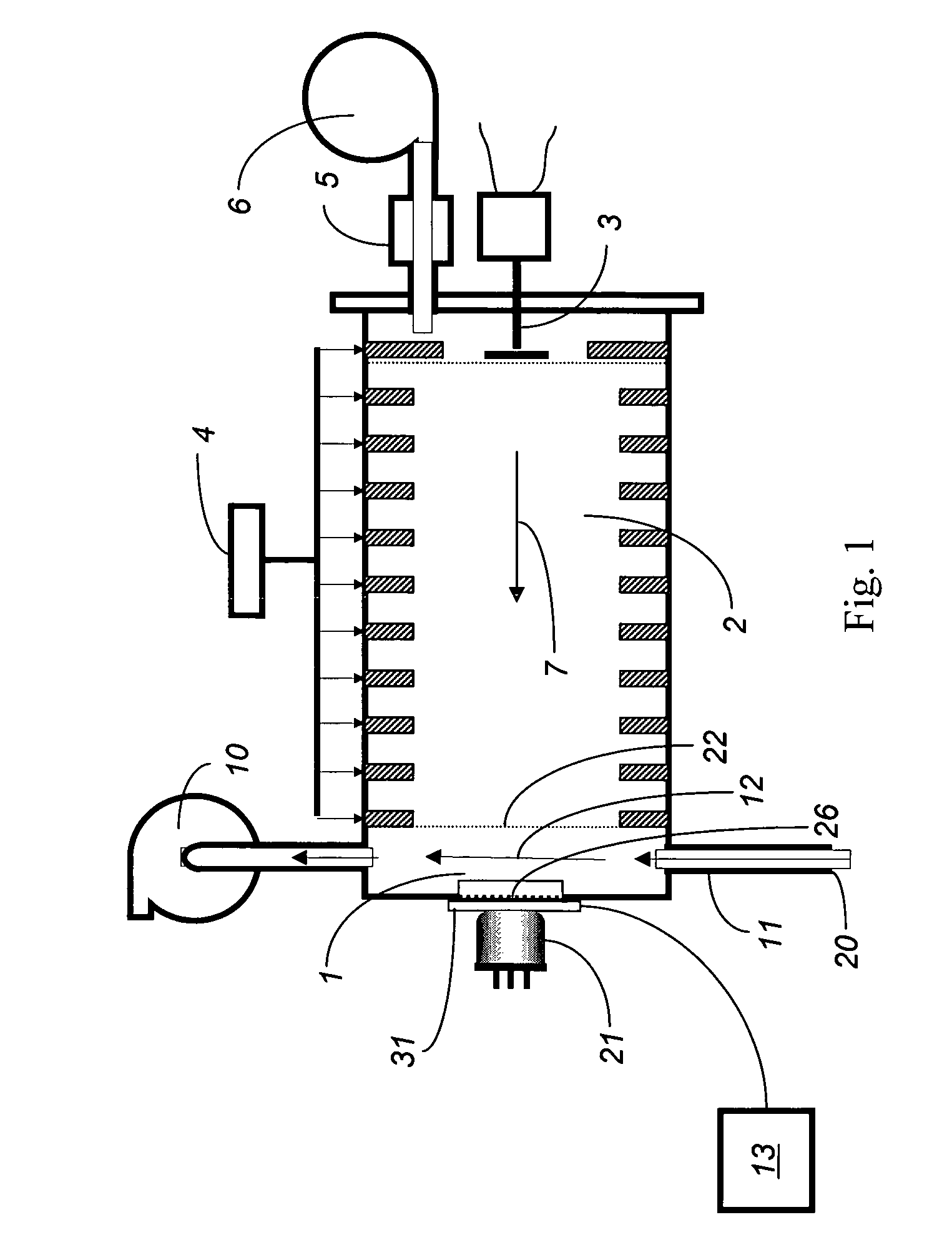
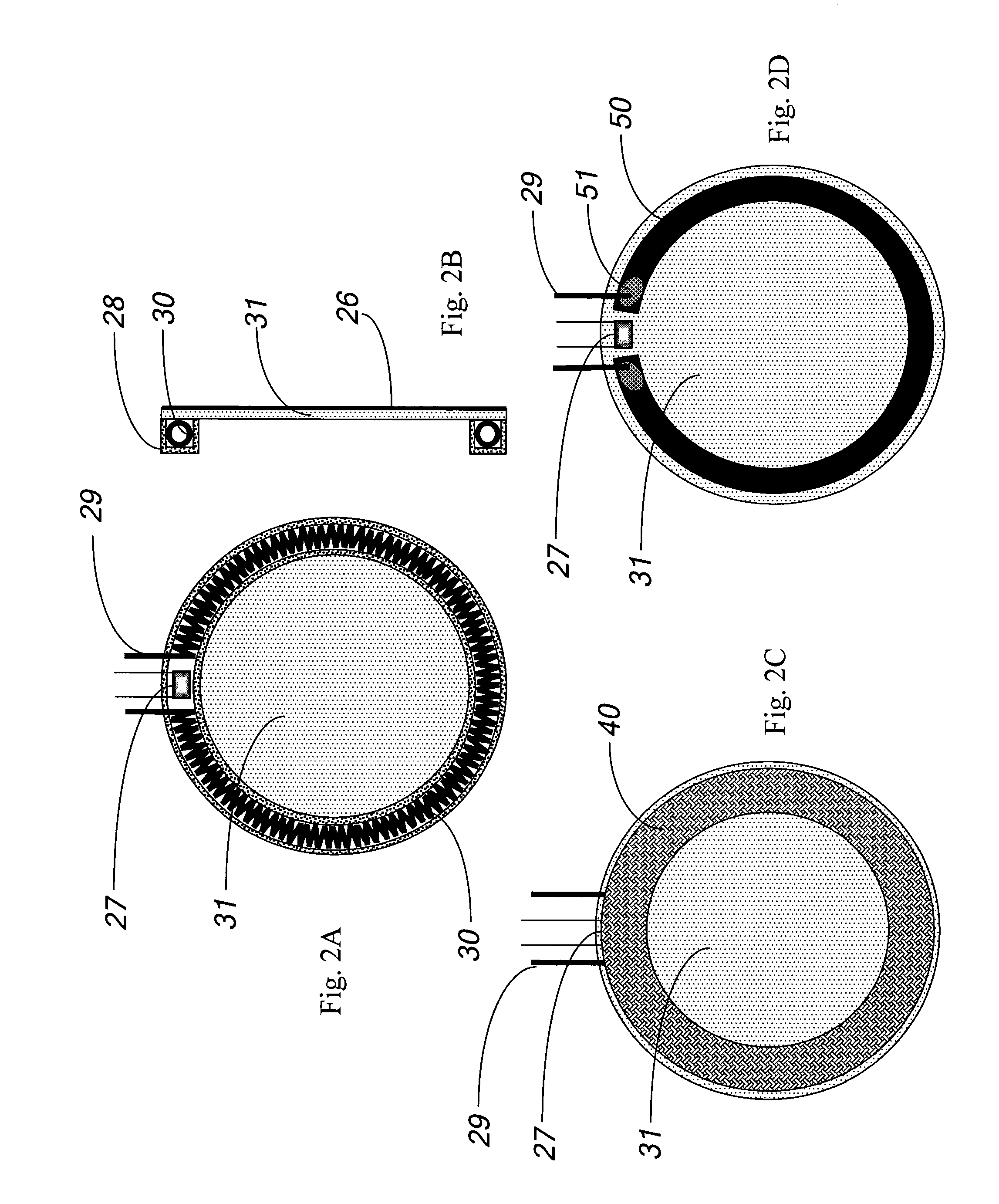
[0035]Referring to FIG. 1, an explosive detection system according to an embodiment of the system described herein uses an Ion Mobility Spectrometer (IMS) that senses negative ions. While any number of a variety of other embodiments may be used, the embodiment illustrated in FIG. 1 includes an ion source 1, a drift tube 2, a current collector 3, a source of negative operating voltage 4 and a source of purified drift gas 5, possibly having gas pump 6 associated therewith. An explosive detection system may also have a gas pump 10 for gas sampling and a tubular connection 11 between the ion source 1 and an external gas sampling inlet 20 that includes an orifice. Gas flow for drift gas 7 moves through the drift tube 2. A sampling gas flow 12 moves from the external gas sampling inlet 20 through the tubular connection 11 and ion source 1 to the gas pump 10. The ion source 1 may include of an optically transparent window 31 through which ultraviolet photons from a flash lamp 21 may pass t...


PUM


Abstract

An explosive detection system based on an ion mobility spectrometer detects the presence of trace molecules in air. Such instruments require an ion source to ionize the trace molecules. An ion source that does not require a radioactive source to operate can use the photoelectric effect to produce electrons. Such a photoelectric ion source will gradually be contaminated and lose its photoelectron emission properties when operated in the air. The photocathode of the ion source can be automatically regenerated by a heater in thermal communication with the photocathode. The heater may be activated when the photoelectron emission falls below a predetermined value ro may run or cycle continuously.

Description

CROSS-REFERENCE TO RELATED APPLICATIONS[0001]This application claims priority to U.S. provisional patent application No. 60 / 708,002 filed Aug. 12, 2005 and is a continuation-in-part of U.S. patent application Ser. No. 10 / 890,820 filed on Jul. 14, 2004 (now U.S. Pat. No. 7,098,672) which is a continuation-in-part of U.S. patent application Ser. No. 10 / 349,491 filed on Jan. 22, 2003 (now U.S. Pat. No. 6,828,795), which is a continuation-in-part of U.S. patent application Ser. No. 10 / 295,039 filed on Nov. 14, 2002 (now abandoned) and U.S. patent application Ser. No. 10 / 295,010 filed on Nov. 14, 2002 (now U.S. Pat. No. 6,861,646), both of which claim priority to U.S. provisional application No. 60 / 357,394, filed Feb. 15, 2002, U.S. provisional application No. 60 / 357,618, filed Feb. 15, 2002, and U.S. provisional application No. 60 / 363,485, filed Mar. 12, 2002, all of which are incorporated herein by reference. This application is also a continuation-in-part of U.S. patent application Se...

Claims


Application Information

Patent Timeline
Patent Type & Authority Patents(United States)
IPC IPC(8): H01J49/10
CPCH01J40/06G01N27/622
Inventor BUNKER, STEPHEN N.KRASNOBAEV, LEONID
Owner LEIDOS SECURITY DETECTION & AUTOMATION INC
Why Eureka
Try Eureka