Digital phase-locked loop

a phase-locked loop and digital technology, applied in the field of phase-locked loop circuits, can solve the problems of large chip area of analog loop filters and relatively complex design compared to many conventional digital pll designs

Inactive Publication Date: 2009-08-18
BROADCOM INT PTE LTD
View PDF20 Cites 59 Cited by
  • Summary
  • Abstract
  • Description
  • Claims
  • Application Information

AI Technical Summary

Problems solved by technology

However, such components in these analog loop filters require a relatively large amount of chip area on an integrated circuit containing the PLL.
Although the digitally controlled PLL described in the article occupies an area of only approximately 0.07 mm2, its design is relatively complex compared to many conventional digital PLL designs.

Method used


Image

  • Digital phase-locked loop
  • Digital phase-locked loop
  • Digital phase-locked loop

Examples


Embodiment Construction

[0018]In the following description, like reference numerals indicate like components to enhance the understanding of the invention through the description of the drawings. Also, although specific features, configurations and arrangements are discussed hereinbelow, it should be understood that such is done for illustrative purposes only. A person skilled in the relevant art will recognize that other steps, configurations and arrangements are useful without departing from the spirit and scope of the invention.

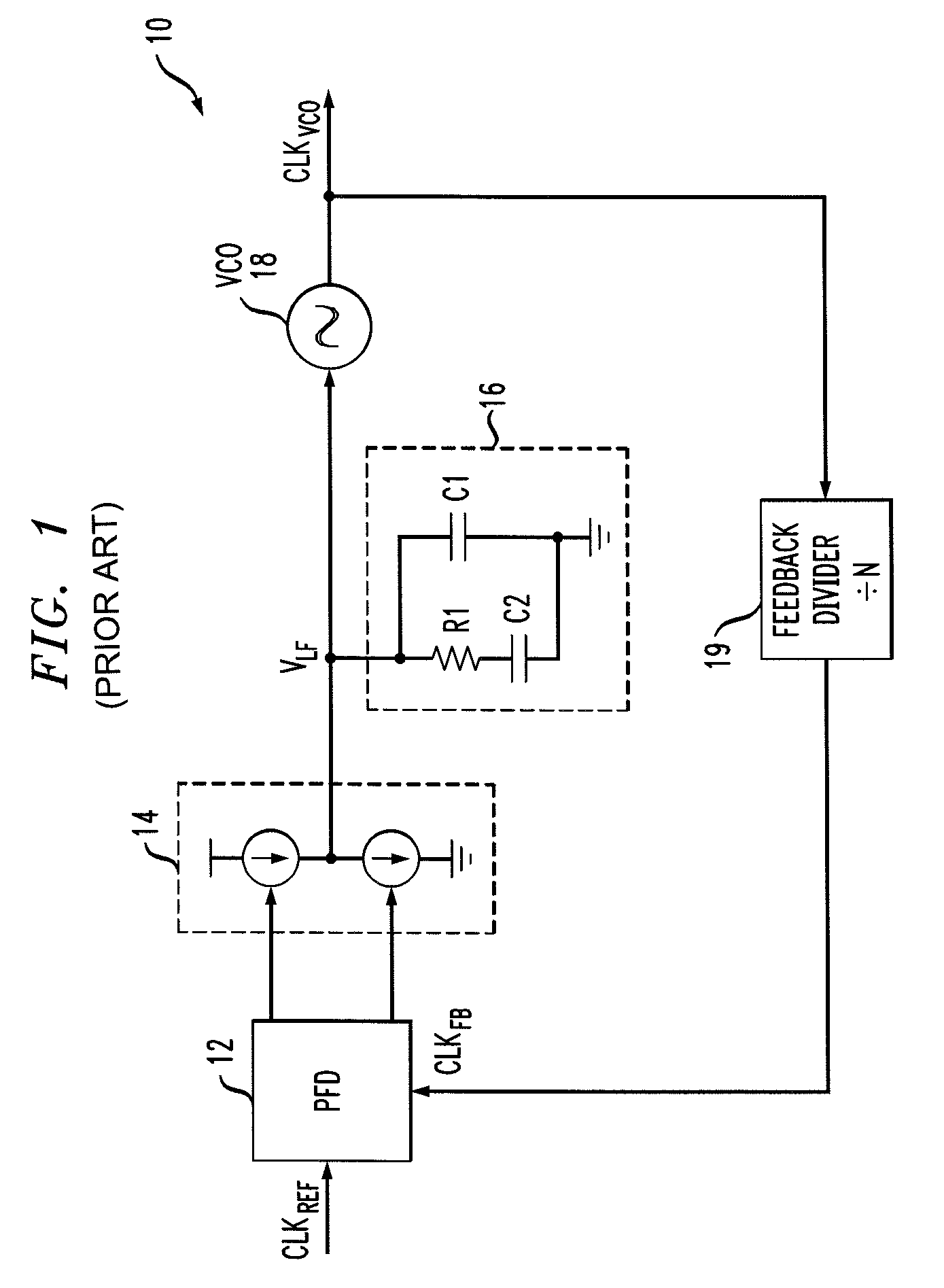
[0019]Referring now to FIG. 1, shown is a simplified schematic diagram of a conventional phase-locked loop (PLL) 10. As discussed previously herein, a PLL is a circuit that generates a periodic output signal, or clock, that has a constant phase and frequency relationship with respect to a periodic input signal. The PLL 10 includes a phase / frequency detector (PFD) 12, a charge pump (shown as 14), a loop filter (shown as 16), a voltage-controlled oscillator (VCO) 18, and a feedback...


PUM


Abstract

Embodiments of the invention include an integrated circuit including a phase-locked loop (PLL). The integrated circuit includes a phase detector, a frequency detector, a loop filter, a digitally-controlled oscillator and a corresponding plurality of frequency dividers. The phase detector generates a first binary output based on a phase comparison of a reference clock signal to a plurality of clock phase inputs. The frequency detector generates a second binary output based on a frequency comparison of the reference clock signal to the clock phase inputs. The loop filter generates a third binary output based on the first binary output and the second binary output. The DCO feeds back the clock phase inputs, via the frequency dividers, to the phase detector based on the third binary output, and feeds back one of the clock phases to the frequency detector based on the third binary output.

Description

BACKGROUND OF THE INVENTION[0001]1. Field of the Invention[0002]The invention relates to phase-locked loop (PLL) circuits. More particularly, the invention relates to sampling phase detectors in all digital phase-locked loops.[0003]2. Description of the Related Art[0004]A phase-locked loop (PLL) is a circuit that generates a periodic output signal, or clock, that has a constant phase relationship with a periodic input signal. PLLs are closed loop frequency control systems whose operation depends on the detection of the phase difference between the input and output signals of the circuit, and are used in many types of measurement, microprocessor and communications applications.[0005]Typically, a conventional PLL includes a phase / frequency detector (PFD), a charge pump, a loop filter, a voltage-controlled oscillator (VCO) to generate the PLL output clock, and a frequency divider. The PFD measures the difference in phase between an input clock and a feedback clock, which may be the PLL...

Claims


Application Information

Patent Timeline
Patent Type & Authority Patents(United States)
IPC IPC(8): H03D3/24
CPCH03L7/087H03L7/0995H03L7/093H03L2207/50
Inventor AZADET, KAMERANYANG, FUJI
Owner BROADCOM INT PTE LTD
Why Eureka
Try Eureka