Compound archery bow with extended inverted stroke

a compound archery and inverted stroke technology, applied in the field of compound archery bows, can solve the problems of inherently problematic grasping and holding, lack of practical methods for nocking and resting the arrow, and limited energy capacity of traditional bows, so as to achieve the effect of storing and releasing substantially more energy and double the power stroke and energy capacity

Inactive Publication Date: 2009-08-25
NORKUS GREGORY
View PDF8 Cites 79 Cited by
  • Summary
  • Abstract
  • Description
  • Claims
  • Application Information

AI Technical Summary

Benefits of technology

[0009]Other features of an archery bow according to the present invention include an arrow rest placed between excursions of the bowstring between full-drawn and rest, so as to accommodate the extended draw length of the bow. The arrow rest drops away from the path of the bowstring and the arrow when the arrow is released, to avoid interference between the arrow rest and the path of the bowstring. A bowstring arrestor mechanism enables placement of the arrow onto the nock and an arrow rest by first placing the bow into a partially-drawn condition, and preventing release of the bowstring from the partially-drawn condition. Embodiments of the bow also include a support that stabilizes the rear portion of the bow by engaging and supporting an arrow release mechanism that draws the bowstring into the fully-drawn condition, and a slide that prevents an unwanted release of the bowstring as the arrow release mechanism draws the bowstring to the full-draw position.

Problems solved by technology

These three factors are the primary limitations to the energy capacity of the traditional bow.
The inverted bow is inherently problematic to grasp and hold due to rotational forces about the grip, lacks practical methods to nock and rest the arrow, and limits the draw-length by the dimensions of the bow.
For these reasons, the inverted bow has never come into practical use.
As in the case of the traditional bow, the power-stroke is reduced by the brace-height and the compound bow is subject to the same factors which limit energy capacity.

Method used


Image

  • Compound archery bow with extended inverted stroke
  • Compound archery bow with extended inverted stroke
  • Compound archery bow with extended inverted stroke

Examples


Embodiment Construction

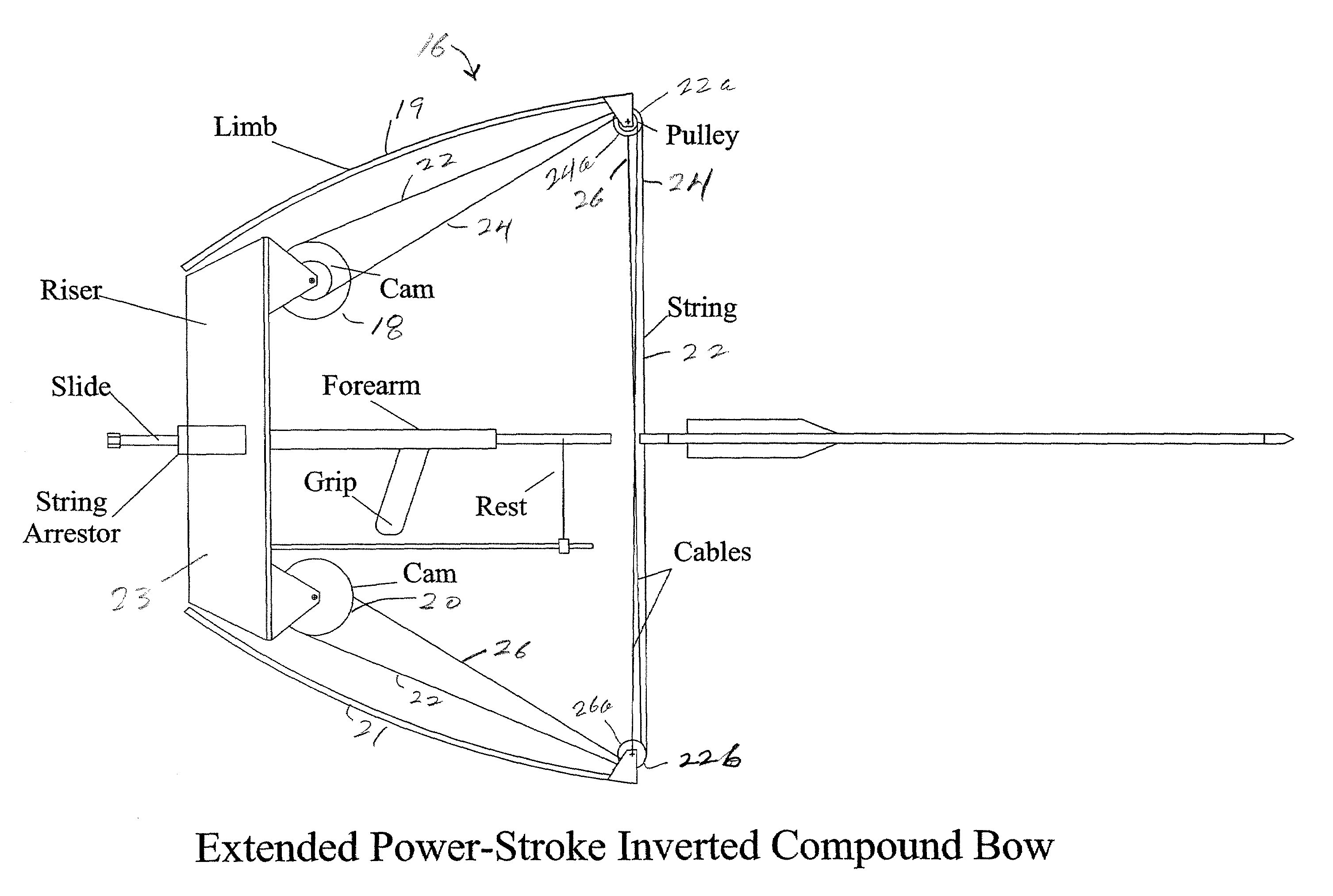
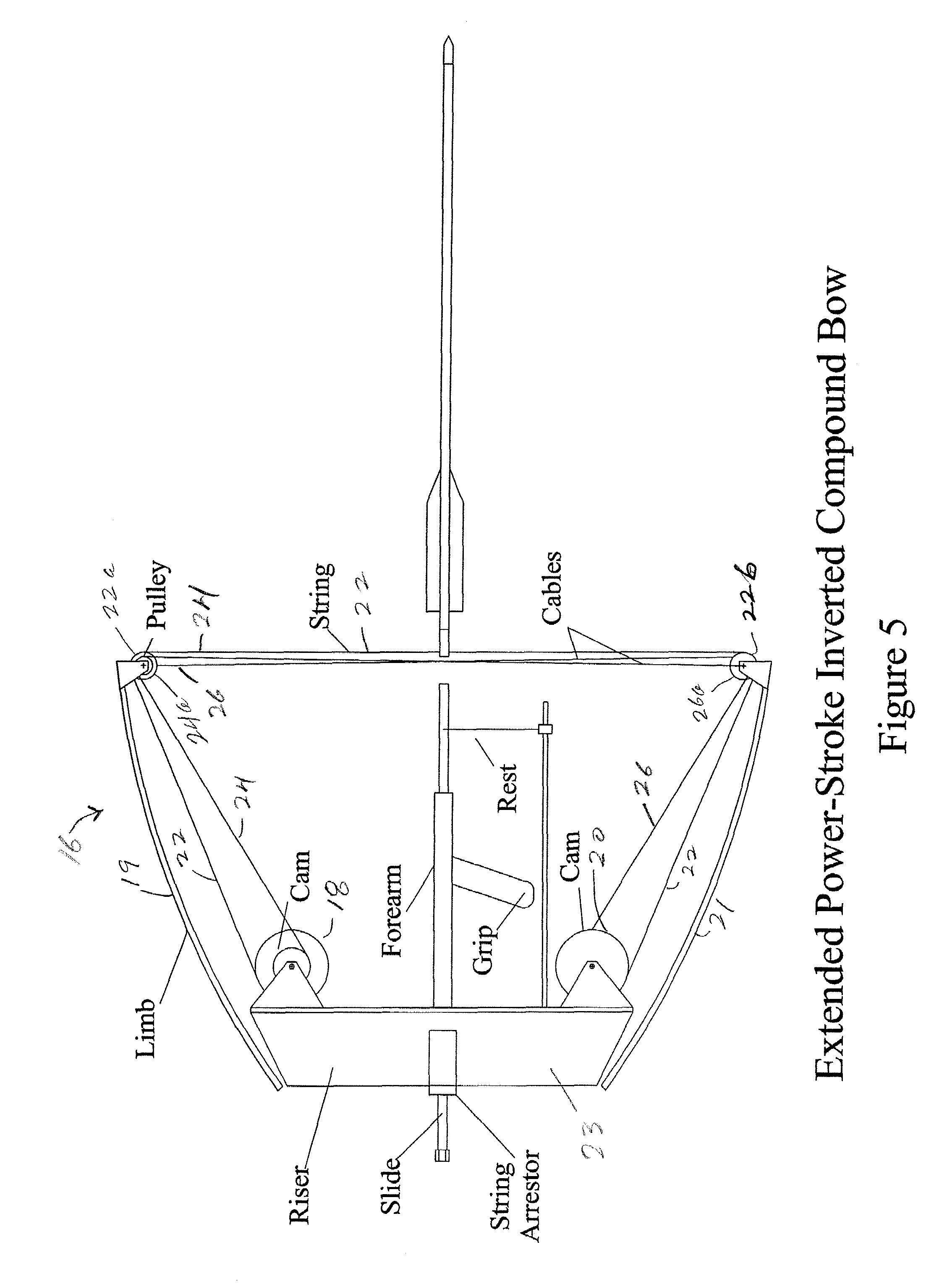
[0025]An archery bow according to the disclosed embodiment is shown generally at 16 in at FIGS. 5 and 7, and includes two counter-rotating cams 18 and 20, a bowstring 22, two cables 24 and 26, and four pulleys 22a, 24a and 22b, 26a at outer ends of the limbs 19 and 21 extending outwardly and forwardly from the riser 23. A forearm extends forwardly from the riser and supports a grip for the hand of an archer The cams 18 and 20 of the bow each contain a groove 28 to receive the bowstring 22 and a groove 30 to receive the respective cable 24 or 26. The cams 18 and 20 rotate on axes supported on the riser 23 and revolve through approximately 720 degrees of rotation at full-draw. Therefore, the bowstring 22 wraps around each cam twice in the bowstring groove 28. The grooves 30 for the cables 24 and 26 are helical in shape and also have the capacity for two full wraps. At any point of rotation the string and cable tension are opposite and proportional to the inverse ratio of the radii fro...


PUM


Abstract

An inverted compound archery bow including an extended-capacity cam system having two cams, each cam engaging the bowstring and separate cables extending to limbs of the bow. The bowstring and cables are counter-wound on the cams, producing tension opposite and proportional to the inverse ratio of windings. Drawing the bowstring winds the cables onto the cams, producing limb tension that propels an arrow when the bowstring is released. An arrow rest located between full-draw and rest excursions of the bowstring accommodates the extended draw length of the bow. A bowstring arrestor engages the bowstring at an intermediate-draw position. A slide stabilizes and supports a rear portion of the bow, and a receptacle on the slide engages an adapter for a bowstring release mechanism.

Description

CROSS-REFERENCE TO RELATED APPLICATION[0001]This application claims the benefit of provisional application No. 60 / 713,186 filed Aug. 30, 2005.FIELD OF THE INVENTION[0002]This invention relates in general to archery bows, and relates in particular to inverted compound archery bows.BACKGROUND OF THE INVENTION[0003]A conventional archery bow (FIG. 1) converts the mechanical work of drawing the bowstring into potential energy stored in the spring tension of the limbs which is released as the kinetic energy of the arrow. According to the laws of physics the work input, stored potential energy, and released kinetic energy are equivalent except for frictional and dynamic losses.[0004]The energy capacity of the traditional bow, shown in FIGS. 1 and 2, is the product of the draw-weight and power-stroke. The power-stroke is the draw-length minus the brace-height (FIG. 2). In the design of the traditional bow, the brace-height provides clearance for the gripping hand by limiting the forward tr...

Claims


Application Information

Patent Timeline
Patent Type & Authority Patents(United States)
IPC IPC(8): F41B5/10
CPCF41B5/0094F41B5/10F41B5/1469F41B5/143F41B5/105
Inventor NORKUS, GREGORY
Owner NORKUS GREGORY
Why Eureka
Try Eureka