Brake hydraulic pressure control unit for vehicle

a technology for controlling units and brakes, which is applied in the direction of brake types, brake components, brake systems, etc., can solve the problems of increasing the lateral width (horizontal dimension) of the hydraulic block, the control unit cannot be mounted on the vehicle, and the mounting difficulty of the control unit on the vehicle, so as to reduce the width of the brake and be mounted more easily

Inactive Publication Date: 2009-08-25
ADVICS CO LTD
View PDF5 Cites 9 Cited by
  • Summary
  • Abstract
  • Description
  • Claims
  • Application Information

AI Technical Summary

Benefits of technology

[0009]An object of the present invention is to reduce the width of a brake hydraulic pressure control unit of the type in which the motor and the electronic control unit are mounted on one and the opposite sides of the hydraulic block so as to face each other so that the unit can be mounted more easily on a vehicle.
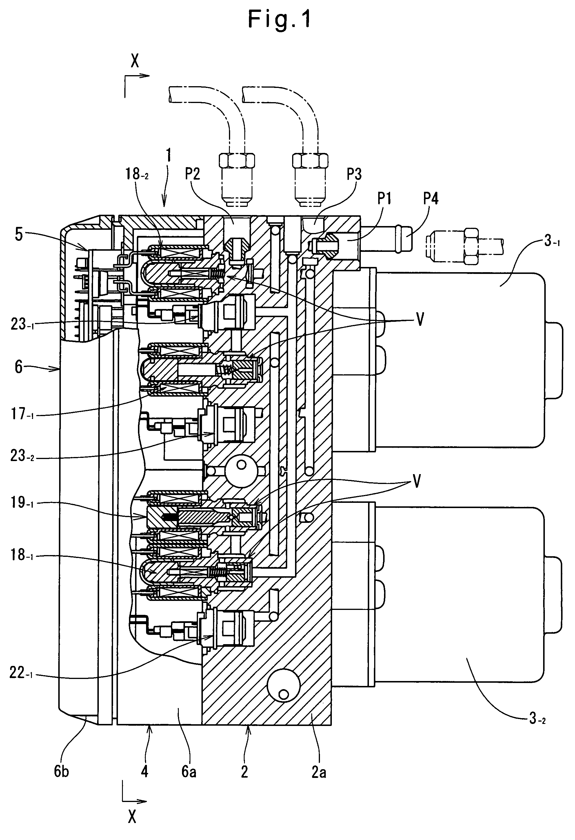
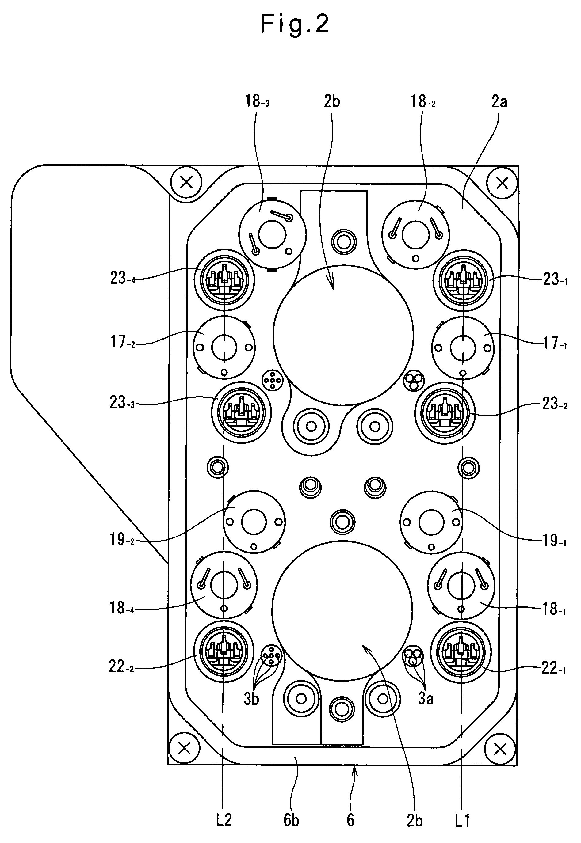
[0016]With this arrangement, because the component parts forming the first and second hydraulic circuits are disposed in the first and second vertically elongated areas on the right-hand and left-hand sides of the pump mounting portions, respectively, it is possible to minimize the lateral width of the unit while avoiding interference of brake fluid passages with the respective component parts of the first and second hydraulic circuits. Since the component parts forming each of the first and second hydraulic circuits are arranged in the corresponding vertically elongated area so as to overlap each other in a direction perpendicular to the vertical axis, it is possible to further reduce the lateral width of the unit.
[0018]By using rotary pumps instead of piston pumps, it is possible to provide a quieter and smaller brake hydraulic pressure control unit.
[0019]The motors may be either brush motors or brushless motors. But for higher performance of the brake hydraulic pressure control unit, brushless motors are advantageous.
[0020]By using brushless motors instead of brush motors, it is possible to improve the responsiveness of the brake hydraulic pressure control unit, and thus its performance.

Problems solved by technology

If such a brake hydraulic pressure control unit, which is mounted in the engine room of a vehicle, is too large in size (external dimensions), it may not be received in the installation space in the engine room according to the type of vehicle, and thus may not be mounted on the vehicle.
This naturally results in increased lateral width (horizontal dimension) of the hydraulic block, thus making it more difficult to mount the control unit on a vehicle.
It is difficult to mount such control units in engine rooms designed such that vertically elongated units can be more easily mounted therein.
This naturally results in increased lateral width of the hydraulic block.

Method used


Image

  • Brake hydraulic pressure control unit for vehicle
  • Brake hydraulic pressure control unit for vehicle
  • Brake hydraulic pressure control unit for vehicle

Examples


Embodiment Construction

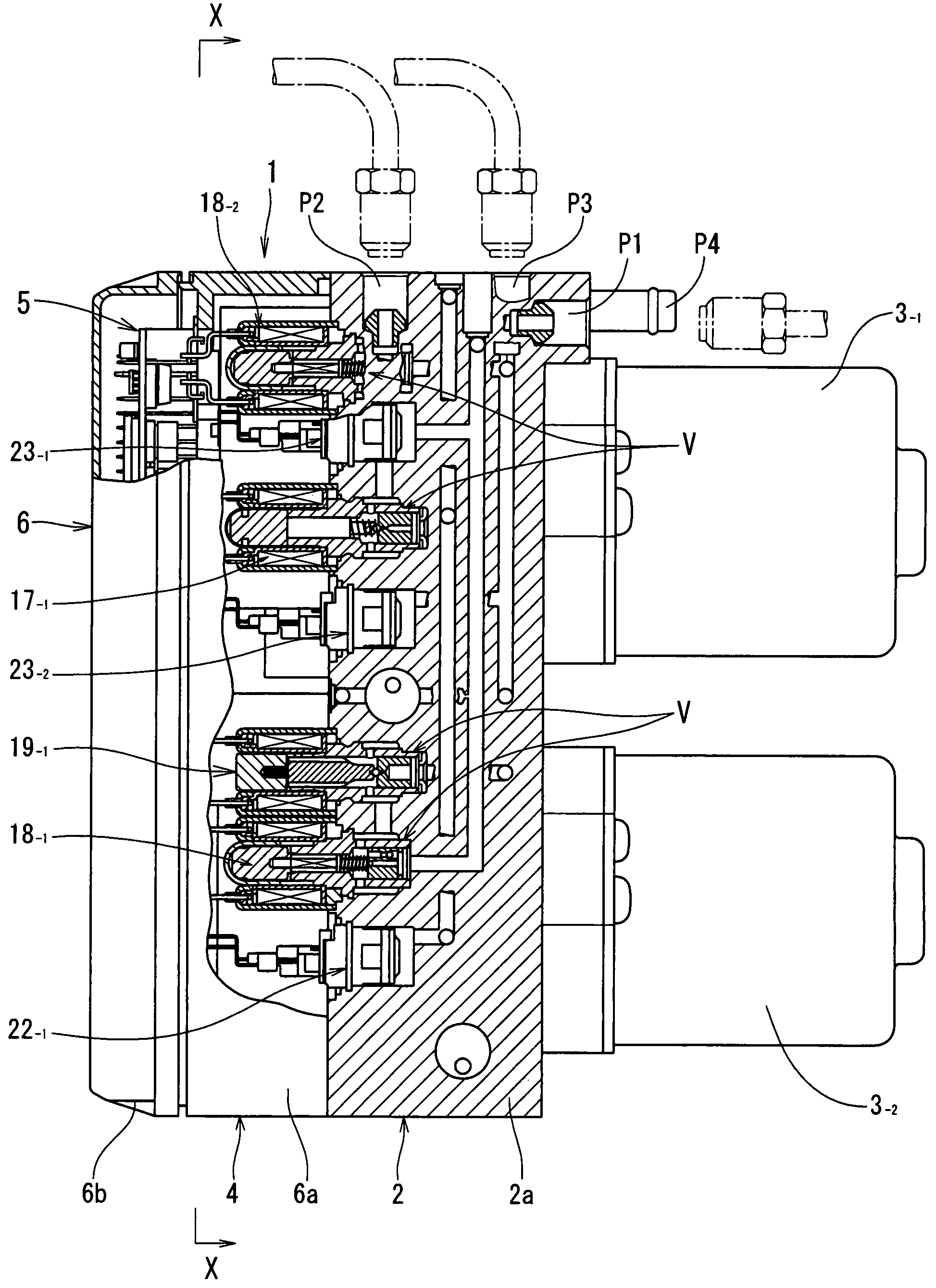
[0028]Now the embodiment of the present invention is described with reference to FIGS. 1 to 4. In the description and the drawings, any plurality of identical elements are individually denoted by identical main numbers with different sub-numbers (-1, -2, -3 . . . ) attached thereto. FIGS. 1 to 3 show a brake hydraulic pressure control unit 1 embodying the present invention, which comprises a hydraulic block 2, motors 3-1 and 3-2, and an electronic control unit 4.

[0029]FIG. 4 shows a circuit configuration of a brake system of the brake-by-wire type which includes four pumps each provided for one of the four wheels of the vehicle, and two motors each for individually driving two of the four pumps. The brake hydraulic pressure control unit of FIGS. 1 to 3 is used in the brake system of FIG. 4. The brake system of FIG. 4 is first described.

[0030]The brake system of FIG. 4 includes a brake operating member (typically a brake pedal as shown), a stepping force sensor 12 for detecting the d...


PUM


Abstract

A brake hydraulic pressure control unit includes motors mounted on one end of a hydraulic block so as to be aligned along a vertical direction. Each motor drives one of two sets of pumps. Solenoid valves and an electronic control unit are provided at the other end of the hydraulic block. Half of the solenoid valves and other component parts, which form a first hydraulic circuit, are provided in a vertically elongated area on the left-hand side of the pump mounting portions, and the other half of the solenoid valves and other component parts, which form a second hydraulic circuit, are provided in a vertically elongated area on the right-hand side of the pump mounting portions, with the component parts of each of the first and second hydraulic circuits overlapping each other in the lateral direction.

Description

CROSS REFERENCE TO RELATED APPLICATIONS[0001]This application is based on and claims priority under 35 U.S.C. sctn. 119 with respect to Japanese Patent Application No. 2006-220321 filed on Aug. 11, 2006, the entire content of which is incorporated herein by reference.BACKGROUND OF THE INVENTION[0002]The present invention relates to a brake hydraulic pressure control unit for a vehicle for controlling hydraulic pressures in the wheel cylinders mounted to the respective wheels of the vehicle based on commands from an electronic control unit.[0003]Such brake hydraulic pressure control units, which are used in vehicle hydraulic brake systems having such functions as anti-lock brake control (ABS) and electronic stability control (ESC) functions, comprise a hydraulic block including a housing, and pumps and solenoid valves mounted to the housing, a motor for driving the pumps, and an electronic control unit including a motor driving circuit and solenoid valve control circuits. The solenoi...

Claims


Application Information

Patent Timeline
Patent Type & Authority Patents(United States)
IPC IPC(8): B60T8/36
CPCB60T8/368B60T13/18B60T8/4081Y10S303/10
Inventor SAKAI, MORIHARU
Owner ADVICS CO LTD
Why Eureka
Try Eureka