Phase adjusting apparatus and a cam shaft phase adjusting apparatus for an internal combustion engine

Inactive Publication Date: 2009-09-01
HITACHI LTD
View PDF4 Cites 7 Cited by
  • Summary
  • Abstract
  • Description
  • Claims
  • Application Information

AI Technical Summary

Benefits of technology

[0031]According to the invention, it is possible to use an intermittent oil supply system to surely prevent reverse rotation (that phase shift in the direction of retarded angle, which is caused by fluctuating torque in the direction of retarded angle, for example, when phase shift in the direction of advanced angle is desired) by fluctuating torque at low speed (low hydraulic pressure), thus enabling producing an effect of high response to the maximum both in the direction of advanced angle and in the direction

Problems solved by technology

Therefore, there is caused a problem that in a state, in which an engine is rotated at low speed as at the time of idling, VTC is decreased in speed of response since hydraulic pressure as supplied is low and so a sufficient driving force cannot be generated.
Thereby, there is caused a problem that when fluctuating torque of the cam shaft gets into high frequency at the time of high speed operation of the engine, opening and closing movements of the check valve cannot follow this and the apparatus cannot function as a phase shift apparatus.
Also, there is caused a problem that a decrease in speed of response is caused corresponding to some reverse rotation generated until a reverse rotati

Method used


Image

  • Phase adjusting apparatus and a cam shaft phase adjusting apparatus for an internal combustion engine
  • Phase adjusting apparatus and a cam shaft phase adjusting apparatus for an internal combustion engine
  • Phase adjusting apparatus and a cam shaft phase adjusting apparatus for an internal combustion engine

Examples


first embodiment

[0073]Consequently, the cam shaft phase adjusting apparatus is driven by hydraulic pressure and fluctuating torque in the direction of advanced angle and reverse rotation can be prevented in a state, in which the electromagnetic valve 12 is controlled in the advanced angle mode as shown in FIGS. 5 and 6, so that phase shift can be achieved at high speed in the direction of advanced angle.

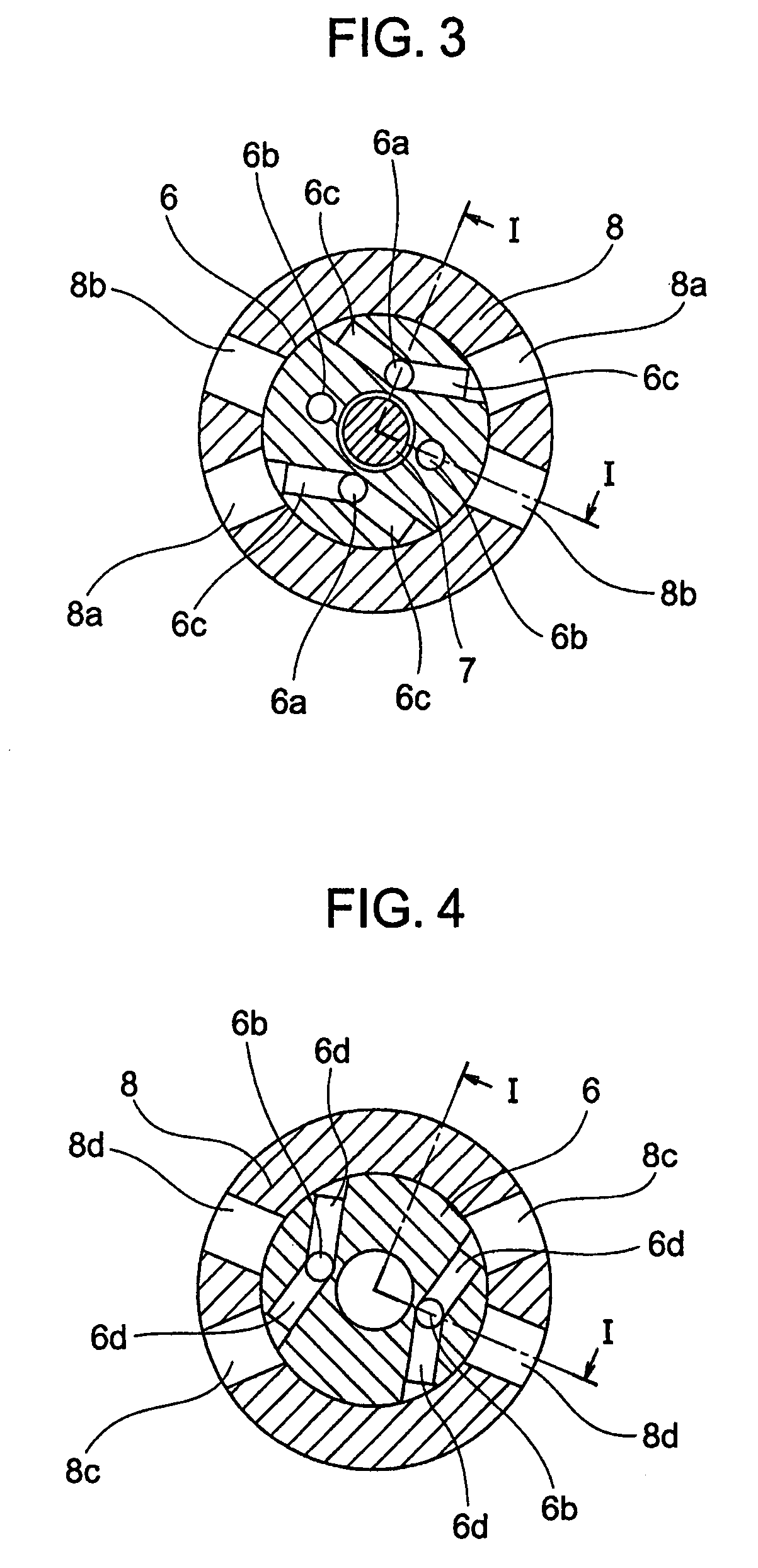
[0074]FIGS. 7 and 8 show a state, in which the retarded angle occasion oil supply paths 8d and the retarded angle occasion oil drain paths 8b in FIGS. 3 and 4 are communicated to the hydraulic power source communication path 13b and the drain communication path 13a, respectively, by the electromagnetic valve 12. With the electromagnetic valve 12, the spool 12b axially driven by the solenoid 12c moves rightward in the drawings to be positioned relative to the body 12a to provide communication between the hydraulic power source communication path 13b and a retarded angle occasion oil supply communica...

second embodiment

[0087]Subsequently, a cam shaft phase adjusting apparatus for internal combustion engine, according to the invention, will be described citing a fundamental function, a configuration example, and a control example of the cam shaft phase adjusting apparatus.

[0088]FIG. 15 is a view illustrating the fundamental function of a cam shaft phase adjusting apparatus according to a second embodiment of the invention. FIG. 16 is a side, cross sectional view showing a cam shaft phase adjusting apparatus for internal combustion engines according to a second embodiment of the invention and taken along the line XVI-XVI in FIG. 17. FIG. 17 is a cross sectional view showing the cam shaft phase adjusting apparatus according to the second embodiment and taken along the line XVII-XVII in FIG. 16. FIG. 18 is a cross sectional view showing hydraulic pressure paths to advanced angle hydraulic chambers in the cam shaft phase adjusting apparatus according to the second embodiment and taken along the line XV...

third embodiment

[0107]Subsequently, a drive system, in which the cam shaft is driven in an advanced angle mode (control), a retarded angle mode (control), or a stationary mode (control to fix to a predetermined phase without being moved by the fluctuating torque) with the use of a configuration of oil path communication shown in FIG. 23, will be described with reference to FIG. 24.

[0108]Cam shaft driving according to the third embodiment is a system, in which a driving force is used properly at low speed (low hydraulic pressure) and at high speed (high hydraulic pressure) such that the fluctuating torque is used as a driving force at low speed and hydraulic pressure is used as a driving force at high speed. In order to properly use a driving force, two control valves having different configurations of oil path communication are used such that one of the control valves is used at low speed and the other of the control valves is used at high speed and that when one of the control valves is used, mut...


PUM


Abstract

A plurality of advanced angle chamber oil paths communicated to advanced angle hydraulic chambers and a plurality of retarded angle chamber oil paths communicated to retarded angle hydraulic chambers according to a change in rotating angle of a cam shaft are provided. The plurality of advanced angle chamber oil paths and the plurality of retarded angle chamber oil paths, respectively, are switched between communication and cut-off according to a rotating angle of the cam shaft. When torque in the direction of advanced angle acts in an advanced angle mode for phase shifting in the direction of advanced angle, the advanced angle hydraulic chambers are caused to communicate to a hydraulic power source and the retarded angle hydraulic chambers are caused to communicate to a drain. Also, at high speed of an engine, in the advanced angle mode, shut-off valves in the advanced angle chamber oil paths and the retarded angle chamber oil paths are opened so that hydraulic pressure is communicated from the hydraulic power source to the advanced angle chambers at all times in the same manner as in the related art.

Description

BACKGROUND OF THE INVENTION[0001]The present invention relates to a control device for a phase angle between two rotating members, and more particular, to a cam shaft phase adjusting apparatus for internal combustion engines, which adjusts timing, at which an intake valve or an exhaust valve driven by a crankshaft through a cam shaft is opened or closed.[0002]Presently, the mainstream in cam shaft phase adjusting apparatuses for internal combustion engines, used in automobile engines, that is, variable valve timing controls (VTC) resides in apparatuses driven by hydraulic pressure supplied from an oil pump, which is belt-driven by an engine. Therefore, there is caused a problem that in a state, in which an engine is rotated at low speed as at the time of idling, VTC is decreased in speed of response since hydraulic pressure as supplied is low and so a sufficient driving force cannot be generated. Reduction in CO2 emission becomes important in a situation, in which regulations for ex...

Claims


Application Information

Patent Timeline
IPC IPC(8): F01L1/34
CPCF01L1/022F01L1/3442F01L1/34409F01L1/024F01L2001/0537F01L2001/34426F01L2001/34469F01L2001/34496F01L2800/00F01L2001/34479F01L2001/3443
Inventor HAYASE, ISAOSUGA, SEIJIICHINOSAWA, YOSHINORITSUKADA, TOMOYA
Owner HITACHI LTD
Why Eureka
Try Eureka