Eureka AIR delivers breakthrough ideas for toughest innovation challenges, trusted by R&D personnel around the world.

Frequency synthesizing device with automatic calibration

a frequency synthesizer and automatic calibration technology, applied in the direction of pulse automatic control, digital transmission, instruments, etc., can solve the problems of inability to lock the frequency, inability to compare analog voltage signals easily, and inability to meet stricter system requirements, etc., to achieve rapid completion of rough tuning for high-speed operations

Inactive Publication Date: 2009-09-01
IND TECH RES INST
View PDF10 Cites 5 Cited by
  • Summary
  • Abstract
  • Description
  • Claims
  • Application Information

AI Technical Summary

Benefits of technology

[0011]An objective of the invention is to provide a frequency synthesizing device that can rapidly complete rough tuning for high-speed operations without being affected by the variation in production process.

Problems solved by technology

If after a period of time the control voltage of the VCO still exceeds a predetermined voltage range, it means the frequency locking is unsuccessful.
Such a device often has to try many bands before a frequency locking is successful.
Moreover, comparing analog voltage signals may be easily affected by the variation in production process.
This is unacceptable for systems that have stricter requirement in the frequency synthesizing time.

Method used


Image

  • Frequency synthesizing device with automatic calibration
  • Frequency synthesizing device with automatic calibration
  • Frequency synthesizing device with automatic calibration

Examples


first embodiment

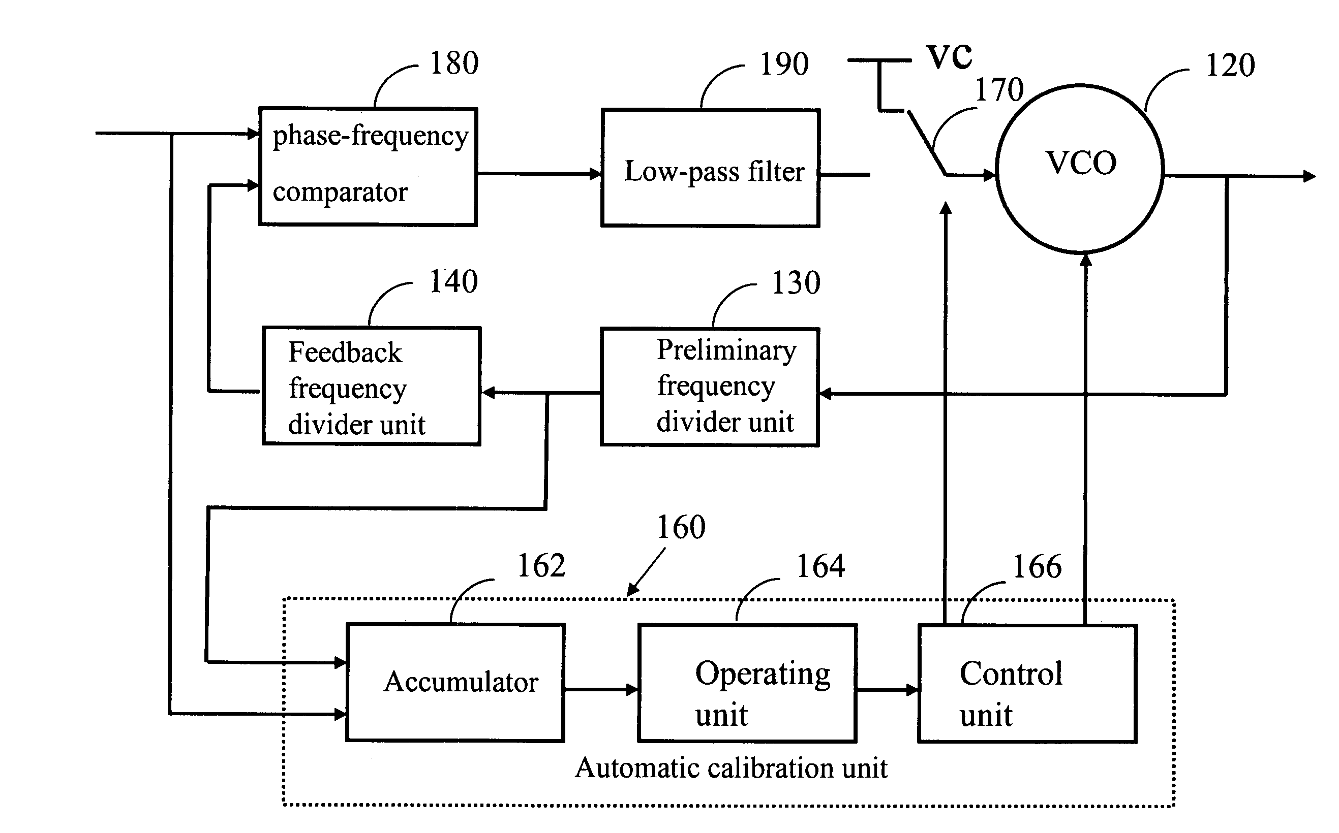
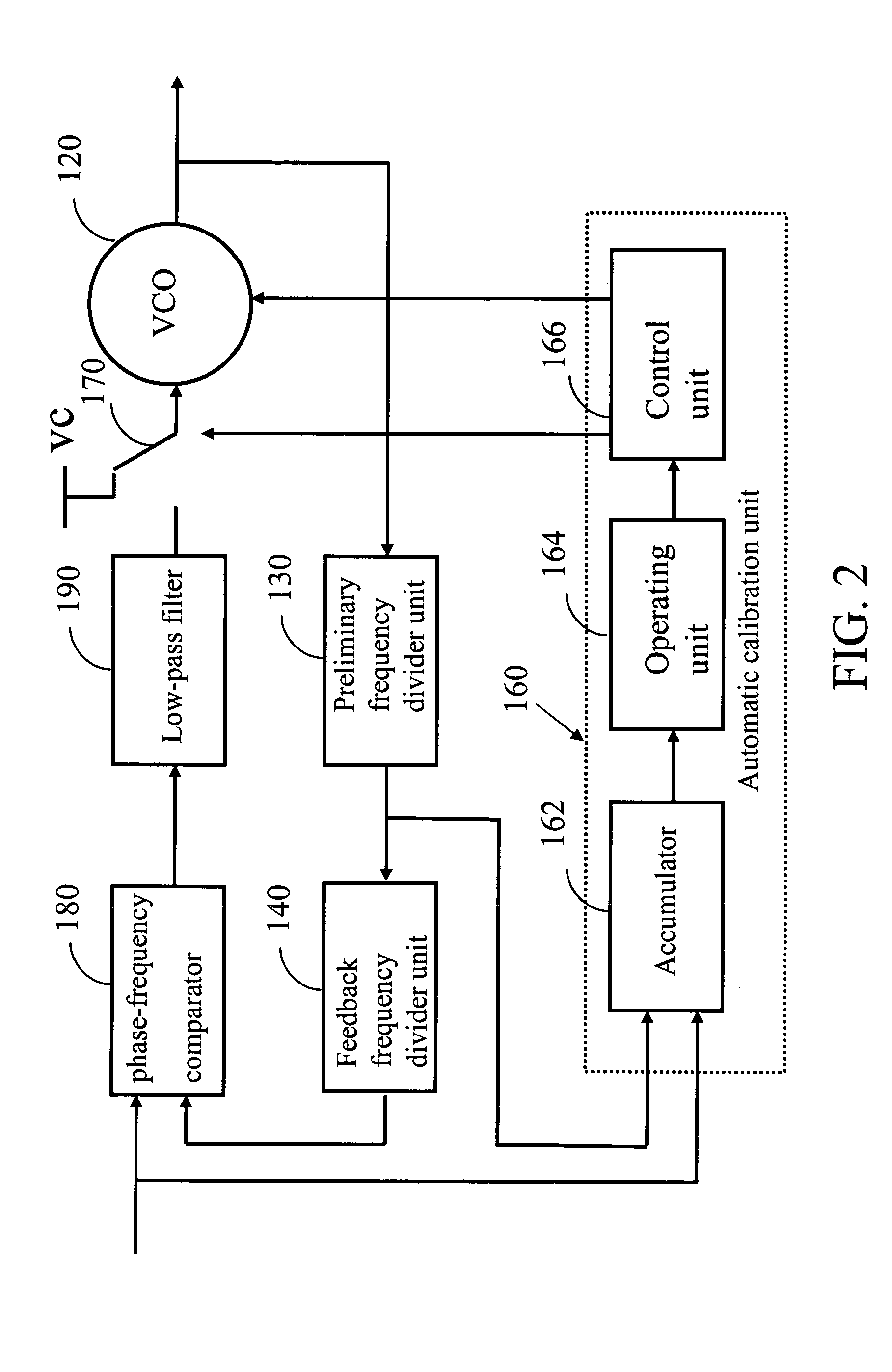
[0020]The frequency synthesizing device with automatic calibration according to the invention, as shown in FIG. 2, has a voltage-controlled oscillator (VCO) 120, a preliminary frequency divider unit 130, a feedback frequency divider unit 140, an automatic calibration unit 160, and a phase-frequency comparator 180. The VCO 120 has many working bands, which may or may not overlap with each other.

[0021]The VCO 120 receives a coarse-tuned signal and a fine-tuned signal, and generates an output signal in the working band set by the coarse-tuned signal. The coarse-tuned signal is an N-bit digital signal, and the fine-tuned signal is an analog signal. The preliminary frequency divider unit 130 receives the output signal and generates an intermediate signal by frequency dividing. The feedback frequency divider unit 140 receives the intermediate signal and generates a feedback signal by frequency dividing. The automatic calibration unit 160 receives the input signal and the intermediate sign...

second embodiment

[0032]Please refer to FIG. 4 for the invention.

[0033]The frequency synthesizing device with automatic calibration includes a VCO 120, a feedback frequency divider unit 140, an automatic calibration unit 160, and a phase-frequency comparator 180.

[0034]The primary difference between the second embodiment and the first embodiment is the omission of the preliminary frequency divider unit. The automatic calibration unit 160 directly receives the output signal. The feedback frequency divider unit 140 also directly receives the output signal. This embodiment is suitable for systems with an automatic calibration unit operating at a sufficiently high frequency.

[0035]The automatic calibration unit 160 receives the input signal and the output signal, and generates a coarse-tuned signal.

[0036]The automatic calibration unit 160 includes an accumulator 162, an operating unit 164, and a control unit 166. The accumulator 162 receives the output signal as the input and computes the number of periods...


PUM


Abstract

A frequency synthesizer with automatic calibration includes a voltage-controlled oscillator, which has several working bands for receiving a coarse-tuned signal and a fine-tuned signal and generating an output signal in the working band of the coarse-tuned signals; preliminary frequency divider unit, which receives the output signal and generates an intermediate signal by frequency dividing; a feedback frequency divider unit, which receives the intermediate signal and generates a feedback signal by frequency dividing; an automatic calibration unit, which receives the input signal and the intermediate signal to generate a coarse-tuned signal; a phase-frequency comparator, which compares the input signal with the feedback signal and generates an error signal according to the frequency and phase differences between the input signal and the feedback signal; and a low-pass filter, which filters the error signal and generates a fine-tuned signal.

Description

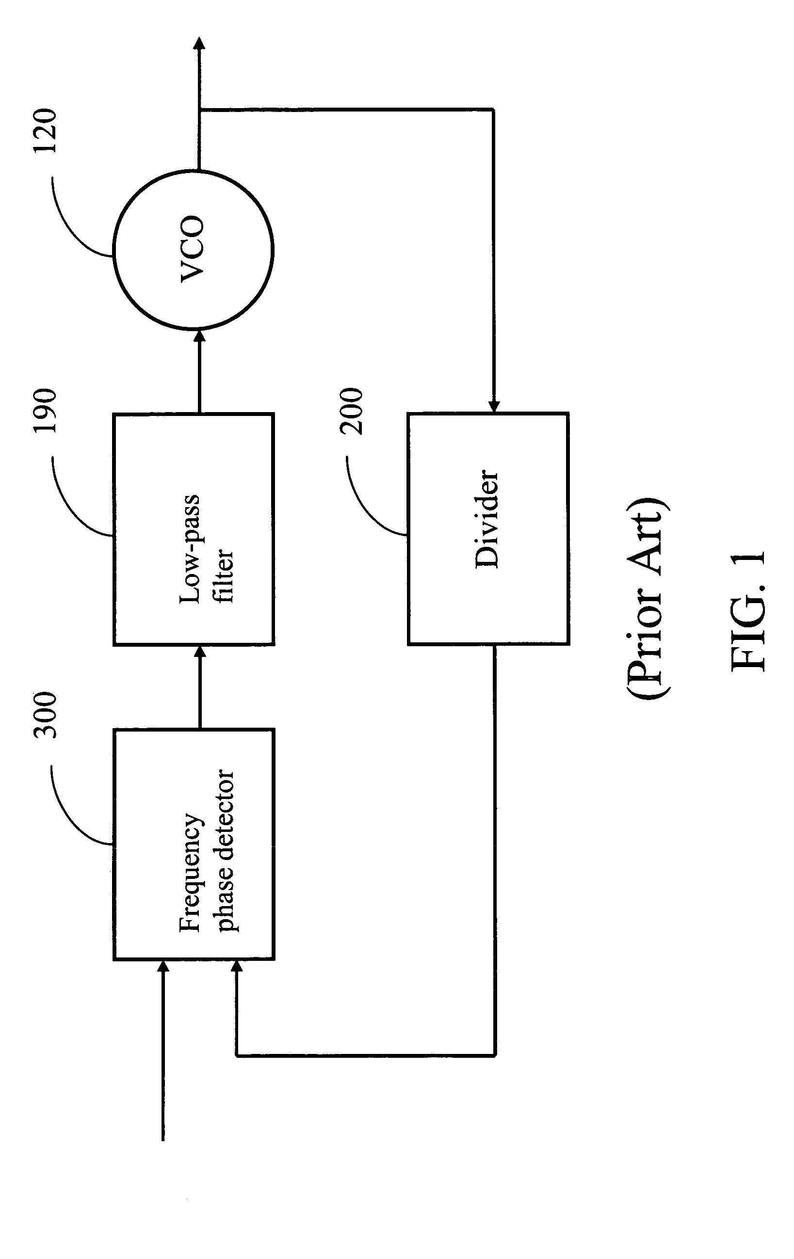
BACKGROUND OF THE INVENTION[0001]1. Field of Invention[0002]The invention relates to a frequency synthesizing device and, in particular, to a frequency synthesizing device and method with automatic calibration.[0003]2. Related Art[0004]The oscillating frequency of a voltage-controlled oscillator (VCO) is determined by inductors and capacitors connected in parallel. One can change the oscillating frequency of the VCO by adjusting the capacitance.[0005]FIG. 1 shows a frequency synthesizer in the prior art. The frequency synthesizer includes a VCO 120, a frequency divider device 200, a frequency phase detector 300, and a low-pass filter 190. The VCO 120 generates an output signal. The frequency divider device 200 removes the frequency of the input signal and produces a feedback signal. The phase detector 300 compares the frequencies and phases of the input signal and the feedback signal. If the frequency of the input signal is higher than that of the feedback signal, the control voltag...

Claims


Application Information

Patent Timeline
Patent Type & Authority Patents(United States)
IPC IPC(8): H03D3/24H03L7/10H03L7/16H03L7/183
CPCH03L7/183H03L7/10H03L7/104
Inventor SU, PENG-UNCHEN, CHIH-HUNGSHIH, HORNG-YUAN
Owner IND TECH RES INST
Why Eureka
Eureka Blog
Learn More