Illuminative light communication device

a technology of light communication and light source, applied in the field of illumination light communication, can solve the problems of adverse effects of infrared rays on the human body, e.g. eyes, etc., and achieve the effects of high-quality communication, increased communication rate, and high-quality communication

Inactive Publication Date: 2009-09-01
ICHIMARU
View PDF50 Cites 384 Cited by
  • Summary
  • Abstract
  • Description
  • Claims
  • Application Information

AI Technical Summary

Benefits of technology

[0009]More specifically, a structure such that a data modulator frequency division multiplexes multiple pieces of data, and transmits the resulting data via the power line and that the filter unit selects one of multiple band pass filters with different frequency bandwidths, which constitute a filter unit, and separates data is possible. Alternatively, a structure such that the data modulator time division multiplexes multiple pieces of data, adds tag data to the resulting divided data, and transmits the resulting data and that the filter unit identifies data based on the tag data and selectively separates data is possible.
[0067]According to a ninth aspect of the present invention, data transmission to or from the mobile unit is possible. In this case, the light receiving units and the leaky optical fiber on the mobile unit side may be deployed under the floor of the mobile unit. Thus the leaky optical fiber and the light receiving units on the ground can be deployed between tracks. When carrying out communication, since the mobile unit covers the tracks, optical communication in a dark place is possible. Therefore, influence of disturbance light such as sunlight or street light decreases, thereby providing high quality communication and an increased communication rate.

Problems solved by technology

Moreover, there is fear that infrared rays may adversely influence the human body (e.g., eyes).

Method used


Image

  • Illuminative light communication device
  • Illuminative light communication device
  • Illuminative light communication device

Examples


first embodiment

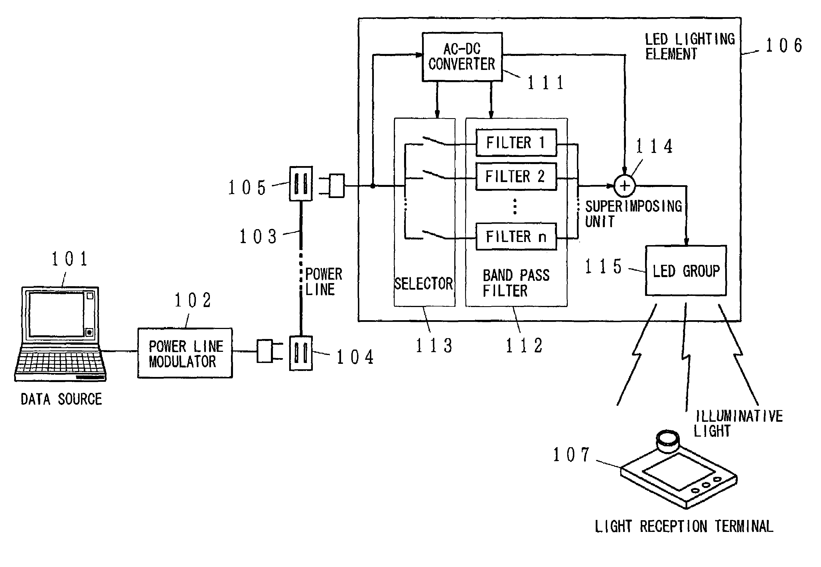
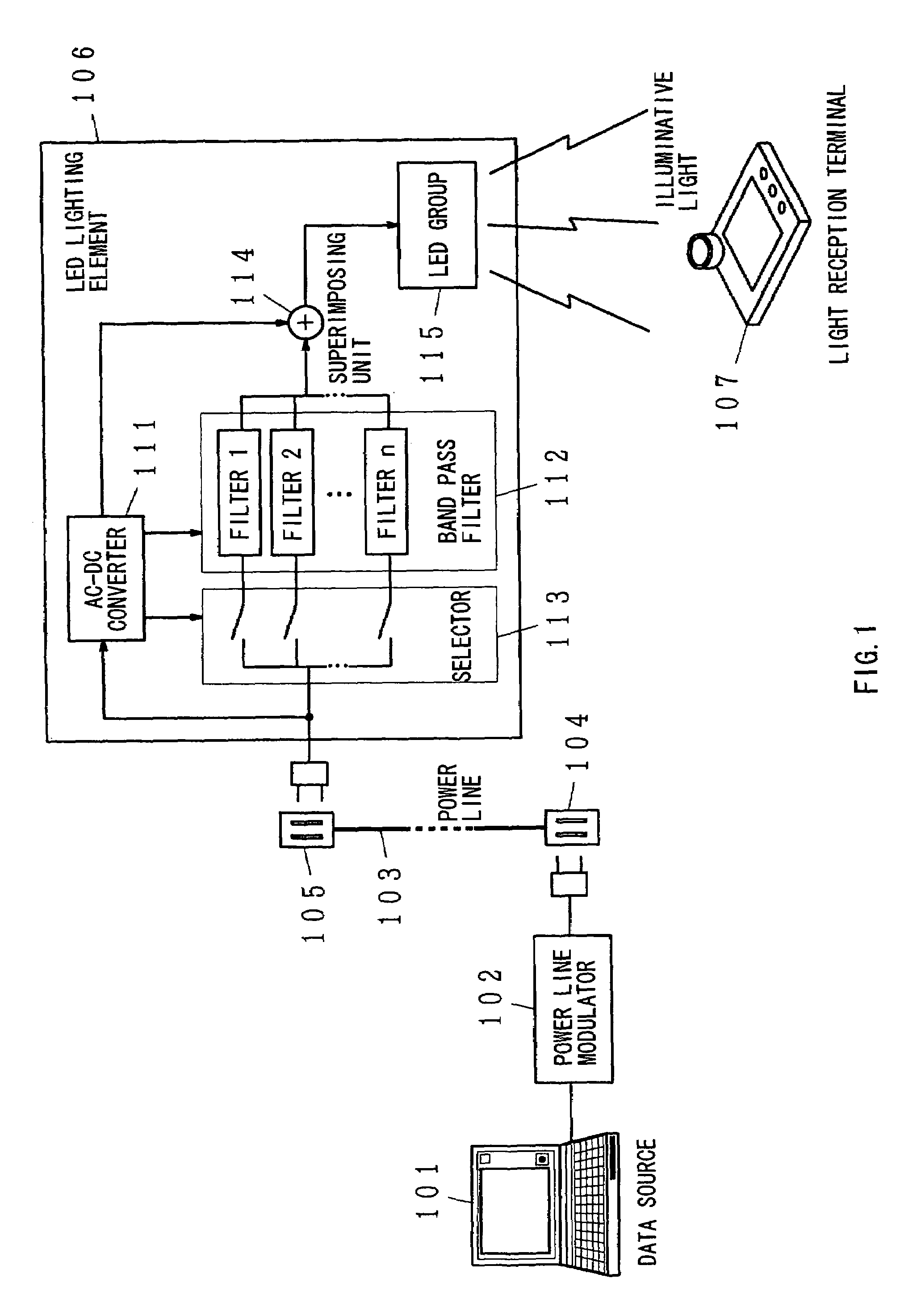
[0134]FIG. 1 is a block diagram of the broadcast system, according to the first aspect of the present invention. In the drawing, 101 denotes a data source, 102 denotes a power-line modulator, 103 denotes a power line, 104 and 105 denote outlets, 106 denotes an LED lighting element, 107 denotes a light reception terminal, 111 denotes an AC-DC converter, 112 denotes a band pass filter, 113 denotes a selector, 114 denotes a superimposing unit, and 115 denotes an LED group. The data source 101 may be constituted by apparatus, such as a TV, a CATV, a radio, and a tuner or a receiver for the CATV, as well as a computer, which are capable of outputting various data. Accordingly, what is broadcast may be various data, such as picture data, music data, sound data, image data, and character data. Moreover, what is broadcast may be a single piece of data or multiple pieces of data; it is assumed here that multiple pieces of data are output.

[0135]The power-line modulator 102 modulates and multi...

second embodiment

[0151]FIG. 3 is a block diagram of a broadcast system, according to the first aspect of the present invention. In the drawing, the same reference numerals are given to the same parts as those in FIG. 1, and repetitive descriptions thereof are thus omitted. 116 denotes a band pass filter, 117 denotes a determination unit, and 118 denotes a selector. In this exemplary structure, an identification code (such as IP, PN code) is assigned to each LED lighting element 106 or each piece of data, and only a specific piece of data is selected based on its own identification code and then broadcast.

[0152]A power-line modulator 102 divides multiple pieces of data from a data source 101 into packets, adds a header to the top of each packet, carries out time division multiplexing, and superimposes the resulting packets of data on the electric power waveform. The header includes an identification code.

[0153]The LED lighting element 106 includes the band pass filter 116, the determination unit 117,...

fifth embodiment

[0323]In the example shown in FIG. 41, for example, the shape of the illuminative light sources 551, according to the present invention, is the same rod shape as striplights as with the example shown in FIG. 35. The illuminative light sources 551 each comprises light emitting devices 521, light reception devices 523, and a controller not shown in the drawing. In addition, the inter-adjacent light source light transmitting / receiving units 552 are provided on the tube and are used for communication between adjacent illuminative light sources 551 when the illuminative light sources 551 are positioned so as to provide multiple fluorescent lamps in parallel. Note that assuming the case of providing three or more of illuminative light sources 551, the inter-adjacent light source light transmitting / receiving units 552 should be provided on both sides of the tube.

[0324]In addition, the inter-lighting element light transmitting / receiving units 553 are provided for communicating with illumina...


PUM


Abstract

The present invention has been developed considering the above-described problems and aims to provide various structures and applications for illuminative light communication. According to the first aspect of the prevent invention, a broadcast system includes an LED light source 115 for lighting, a power line 103 that supplies electric power to the LED light source 115, a data modulator 102 that modulates and multiplexes a plurality of pieces of data, superimposes the resulting signal on an electric power waveform, and then transmits the resulting superimposed signal waveform to the power line 103, and a filter 112 that selectively separates one or more of a plurality of pieces of modulated data on the power line so as to control light intensity or blinking of the LED light source. Data is transmitted through changes in light intensity or blinking of the LED light source.

Description

TECHNICAL FIELD [0001]The present invention relates to a technology that contributes to illuminative light communication.BACKGROUND ART [0002]In recent years, a radio wave communication system has become available along with portable terminals. Recently, shorter wavelength infrared rays have been widely used due to available frequency depletion. Other than available frequency depletion, radio waves may influence medical devices or various precision equipment. Moreover, there is fear that infrared rays may adversely influence the human body (e.g., eyes). As a result, optical communication is in the spotlight as a safe communication method.[0003]Meanwhile, white LEDs are developed owing to the success of development of blue LEDs. The features of white LEDs are: extremely lower power consumption than that of conventional incandescent lamps or fluorescent lamps, small size, and long life. Accordingly, use of white LEDs as a illuminative light source is considered. Another feature of whi...

Claims


Application Information

Patent Timeline
Patent Type & Authority Patents(United States)
IPC IPC(8): H04B10/04G09F9/33H04B3/54H04B10/114H04B10/116
CPCG09F9/33H04B3/54H04B10/1141H04B10/1149H04B10/116H05B37/0263H05B37/0272F21Y2101/02H01L2924/3025F21K9/10F21V33/0052H01L2224/48247H01L2224/48091H01L25/0753H04B2203/5412H04B2203/5458Y02B20/72H01L2924/00014H01L2924/00F21K9/20F21Y2115/10F21K9/65H05B47/185H05B47/195F21S8/08G08B27/00
Inventor NAKAGAWA, MASAOKOMINE, TOSHIHIKOHARUYAMA, SHINICHIROISHIGURE, TAKAAKIKOIKEKITANO, SHOGOSUGAWARA, YASUO
Owner ICHIMARU
Why Eureka
Try Eureka