
Foam barrier heat shield

a foam barrier and heat shield technology, applied in the field ofdamping systems, can solve the problems of high noise and structural vibration in the passenger cabin of a traveling vehicle, high noise and structural vibration of speed tire-road contact,

Inactive Publication Date: 2009-09-08
INTPROP HLDG
View PDF144 Cites 21 Cited by
  • Summary
  • Abstract
  • Description
  • Claims
  • Application Information

AI Technical Summary

Problems solved by technology

Automobiles are by their nature very noisy machines.
Engine combustion, high velocity exhaust flow, rotating bearings, rotating transmission and axle linkages, other high speed and / or high shear moving parts, and high speed tire-road contact all generate a significant amount of noise and structural vibration, particularly at high vehicle speed.
All this noise can make the passenger cabin of a traveling vehicle very uncomfortable for passengers, if not unbearable.
In addition, many automobiles components that generate a substantial amount of noise also generate a substantial amount of heat, e.g., the exhaust manifold, catalytic converter, etc.
If unshielded, heat from the exhaust system may be conducted through the underbody into the passenger compartment, making it uncomfortable for passengers.
Many heat-source components, in addition to generating substantial quantities of heat, also are the source of significant vibration and noise.
This is because many of the sources of heat (for example exhaust gases) also are sources of vibration (due to frictional forces between passing high velocity gas and pipe walls).
The result is that the comfort of automobile passengers in the passenger compartment is diminished because there is insufficient noise or vibration attenuation mechanism to reduce noise emanating from high temperature components such as the catalytic converter.
These conventional technologies all fall short of providing adequate thermal shielding at desirably low weight, and none of them provides any substantial measure of noise abatement.

Method used


Image

  • Foam barrier heat shield
  • Foam barrier heat shield
  • Foam barrier heat shield

Examples


example 1

[0053]Four different heat shields 10 according to the invention were made having a semi-rigid polyurethane foam layer. For each of these four heat shields, the foam layer was made from a precursor foaming composition comprised of the following components in the following total weight percents:

[0054]

Multranol 4035 (sucrose-based polyether polyol)20.61Multranol 3900 (glycerin-based polyether polyol)30.92Water0.77DABCO 33LV (amine catalyst)0.72Metacure T-1 (tin catalyst)0.05DABCO DC 5164 (surfactant)0.52DABCO DC 5169 (surfactant)0.26Mondur MA2300 (allophanate-modified MDI (20-30% NCO))46.15TOTAL =100

[0055]The four heat shields were composed as follows:

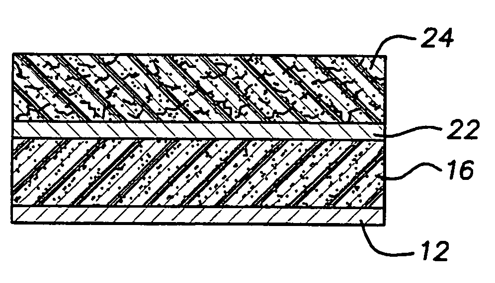
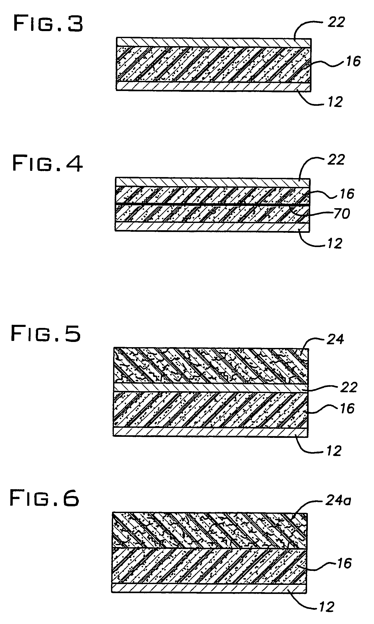
[0056]Invented 1: The foam layer was sandwiched between two opposing aluminum layers each having a thickness of 0.005 inches. The overall thickness of the heat shield was about 0.1 inches, and its area density was about 0.2 lb / ft2.

[0057]Invented 2: The foam layer was sandwiched between two opposing aluminum layers each having a thickness ...

example 2

[0061]Each of the four heat shields of Example 1 was subjected to a hot box temperature drop study to compare the heat shielding characteristics of each with a number of conventional heat shielding and sound dampening materials. Specifically, the four heat shields of Example 1 were compared to:

[0062]“Straight aluminum”, a 0.03-inch thick aluminum sheet which is a conventional underbody heat shield in common use, area density of 0.44 lb / ft2;

[0063]“Laminated aluminum”, which was composed of two sheets of 0.012-inch thick aluminum sheet metal that have been crimped together to form a heat shield—this also is a conventional underbody heat shield, area density of about 0.35 lb / ft2;

[0064]“Shoddy”, a conventional acoustic absorption material composed of pressed cotton—it is typically made by pressing textile cotton waste or scraps into compressed sheets, and is conventionally used to damp noise (NVH) in automobile body panels, area density of 0.24 lb / ft2; and

[0065]“Fiberglass”, which is a ...

example 3

[0069]The four heat shields according to the invention from Example 1, along with the conventional straight aluminum material from Example 2, were subjected to a free-free modal analysis test. Each material was suspended substantially unconstrained by a string to allow for free vibration when impacted. Each of the suspended material samples was then subjected to an impulse from a force hammer. The amount of force supplied on impact and the resulting vibration in each sample were measured to determine the modal resonance or vibration of each material. Results are provided in FIG. 7.

[0070]From the figure, it is evident that all four of the invented heat shields that were tested substantially outperformed the conventional aluminum heat shield in terms of the magnitude of vibration or resonance following the impulse. Accordingly, the invented heat shields themselves are a substantially lesser source of vibrational noise due to their own vibration than the conventional aluminum underbody...


PUM

PropertyMeasurementUnit
Temperatureaaaaaaaaaa
Fractionaaaaaaaaaa
Percent by massaaaaaaaaaa

Abstract

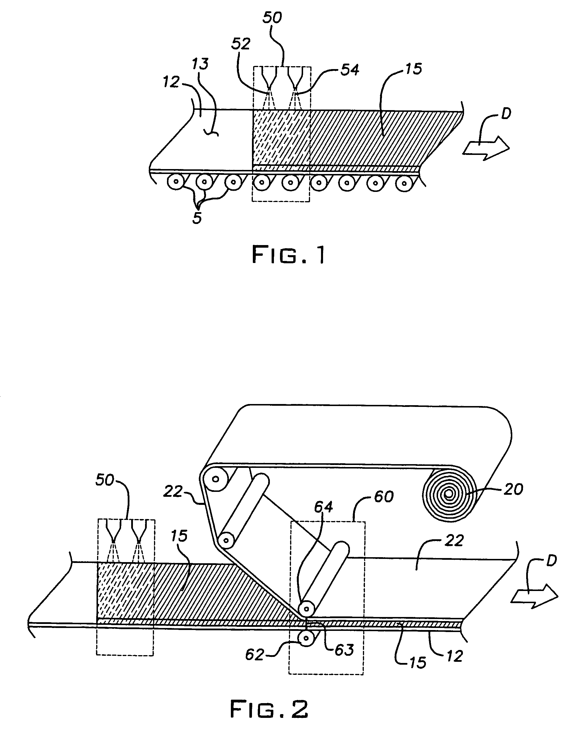
A foam barrier heat shield is provided having a layer of foam adhesively disposed between opposing first and second metallic outer layers. The foam is expanded in between the outer layers and is adhesively formed to the outer layers without the use of a separate adhesive. In addition to shielding heat, the heat shield is effective as a noise barrier and is internally damped against vibration. In a preferred embodiment, the foam is a substantially rigid polyurethane foam that is sufficiently pliant to be bent to and accommodate a particular shape and contour to which the heat shield will conform in use, and it is reversibly deformable acoustical deflections.

Description

[0001]This application claims the benefit of U.S. Provisional Patent Application Ser. Nos. 60 / 475,560 filed Jun. 3, 2003, and 60 / 497,755 filed Aug. 26, 2003, the contents of each of which are incorporated herein by reference in their entirety.BACKGROUND OF THE INVENTION[0002]The invention relates to a damping system for damping vibrational and other noise in passenger vehicles. More particularly, the invention relates to a system that is effective to block noise and vibration, and as a heat shield.[0003]Automobiles are by their nature very noisy machines. Engine combustion, high velocity exhaust flow, rotating bearings, rotating transmission and axle linkages, other high speed and / or high shear moving parts, and high speed tire-road contact all generate a significant amount of noise and structural vibration, particularly at high vehicle speed. All this noise can make the passenger cabin of a traveling vehicle very uncomfortable for passengers, if not unbearable.[0004]In addition, ma...

Claims


Application Information

Patent Timeline
IPC IPC(8): B32B3/26B32B5/18B32B15/08B60R13/08F02B77/11
CPCB32B5/18B32B15/08B60R13/08F02B77/11B60R13/0815B60R13/083Y10T428/237B60R13/0861B60R13/0869B60R13/0884Y10T428/239B60R13/0838Y10T428/24999Y10T428/249981Y10T428/249977B32B15/20B32B2305/02B32B7/12B32B15/095B32B2605/08B32B2266/08B32B5/02
Inventor SCHROEDER, JEFFREY J.MCDONEL, BRADLEY D.CHURBY, SCOTT A.
Owner INTPROP HLDG
Learn More