

Horizontal drilling system with oscillation control
a technology of oscillation control and horizontal drilling, which is applied in the direction of directional drilling, surveying, and well accessories, etc., can solve the problems of high friction, difficult, if not impossible, and high friction of the hole, so as to minimize the wear of drive components, reduce the wear of machine parts, and improve accuracy and smooth oscillation control
- Summary
- Abstract
- Description
- Claims
- Application Information
AI Technical Summary
Benefits of technology
Problems solved by technology
Method used
Image

Examples
Embodiment Construction
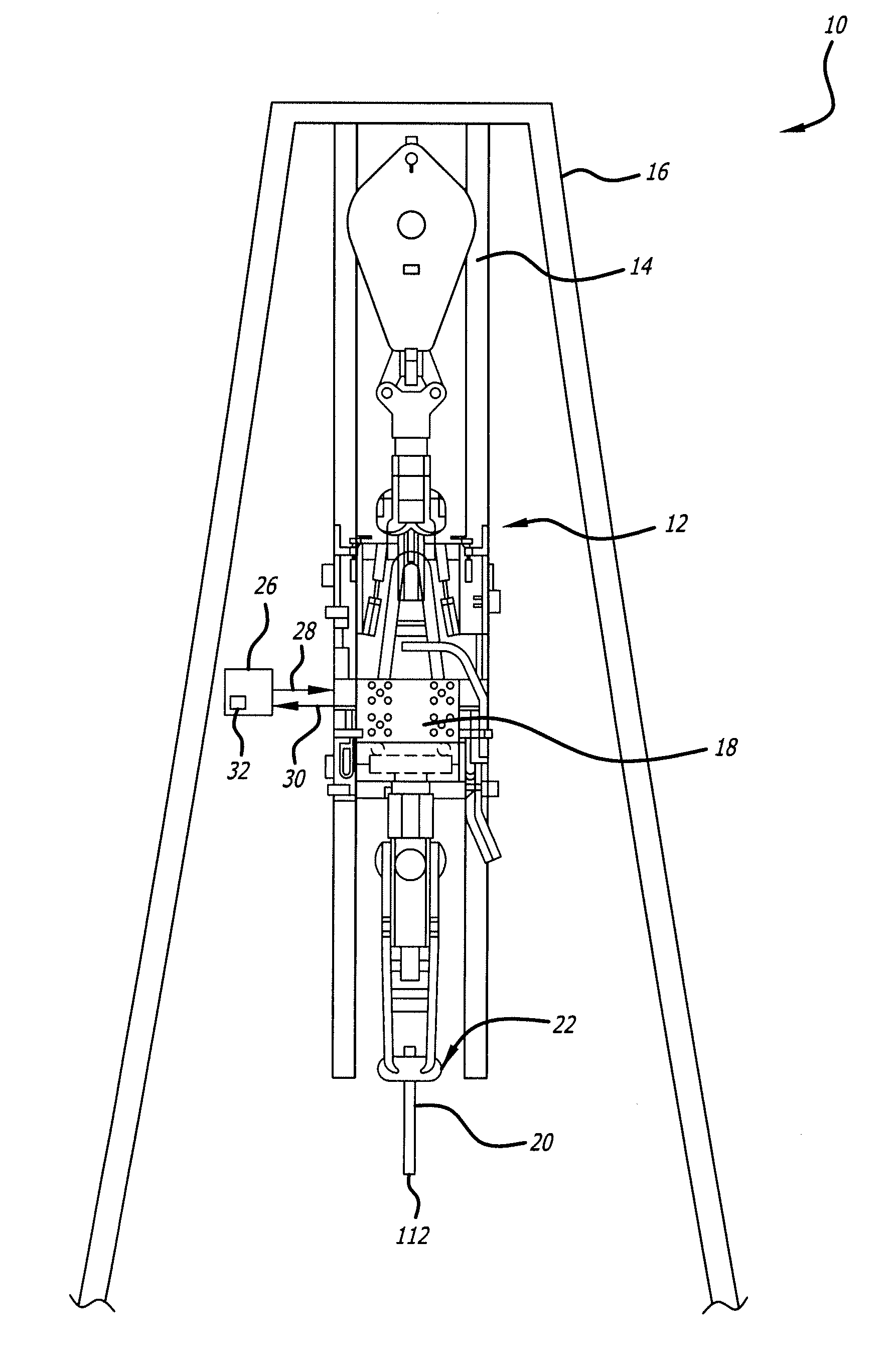
[0021]As shown in FIGS. 1-4, embodiments of the present invention are directed to a horizontal drilling system having a controller for controlling an oscillation procedure of a drill string, whereby the drill string is rotated in a back and forth motion. In one embodiment, the oscillation is controlled by reversing the direction of rotation of the drill string each time a torque limit is exceeded and / or when the drilling motor stalls.
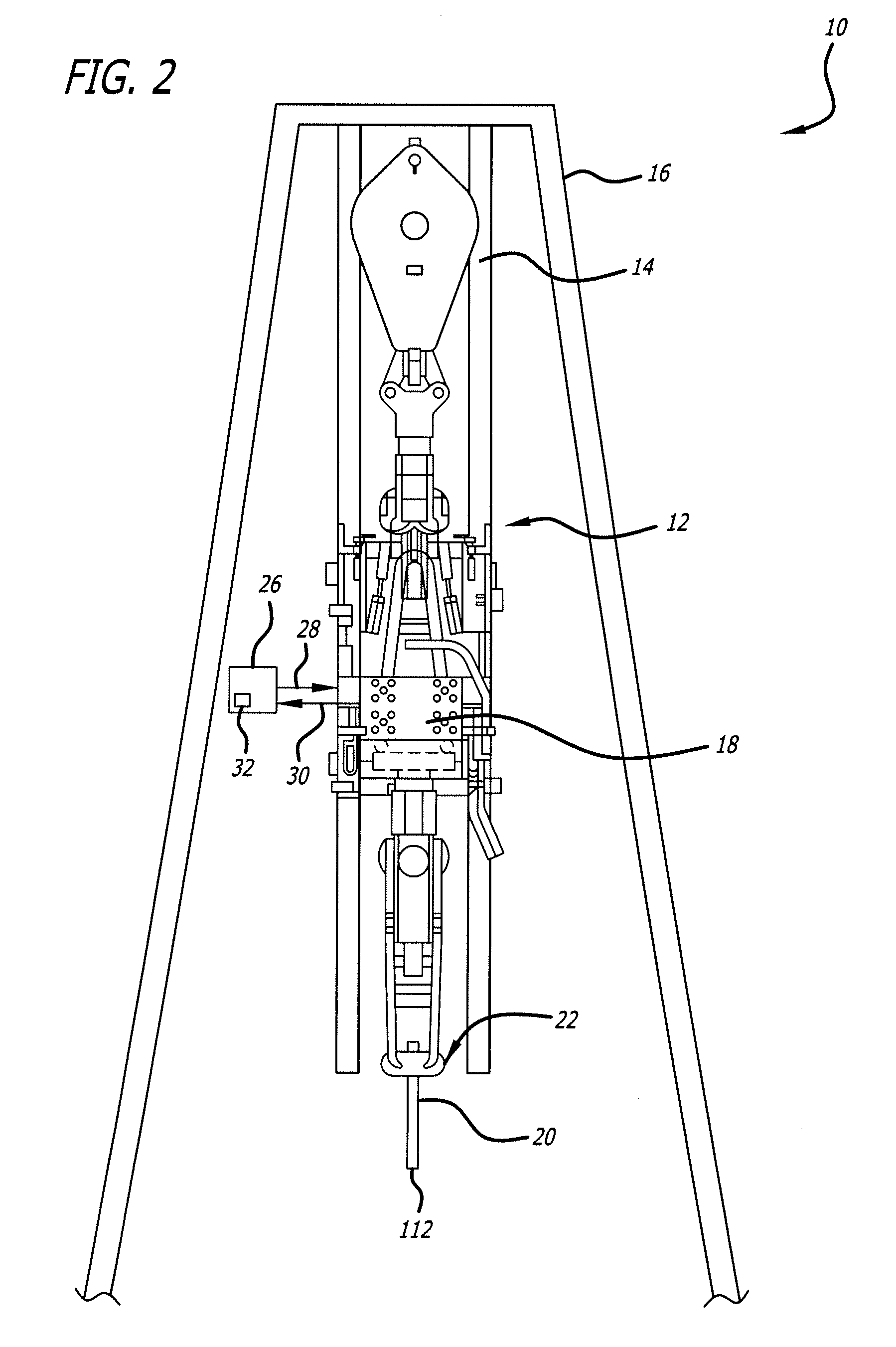
[0022]FIG. 1 is a schematic view of a horizontal drilling system 10 in accordance with an exemplary embodiment of the present invention. As shown in FIG. 2, the horizontal drilling system 10 includes a top drive system 12. The top drive system 12 is vertically movable along vertical supports 14 of a derrick 16. The top drive system 12 includes a top drive motor 18, which imparts translational and rotational forces to a drill string 20. In one embodiment, the top drive system 12 is connected to a pipe running tool 22, which in turn is connected to the dr...
PUM
 Abstract
Description
Claims
Application Information
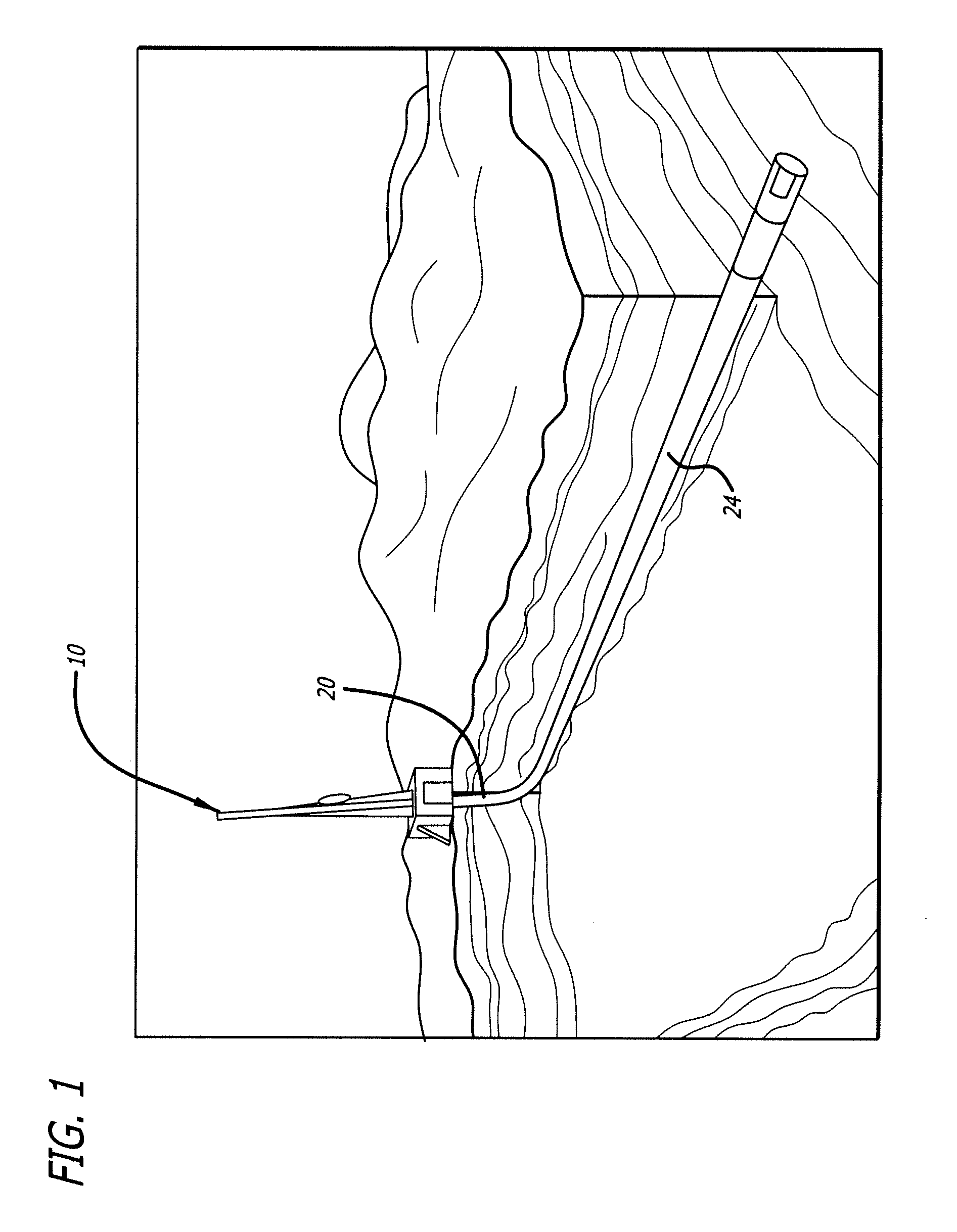