
Power generating device

a power generator and power technology, applied in the direction of electric generator control, speed sensing governor, engine starter, etc., can solve the problems of difficult control of the pressure of the low pressure steam discharged from the turbine, and achieve the effect of increasing the output, and maximum ability of the power generator

Active Publication Date: 2009-09-15
KOBE STEEL LTD
View PDF5 Cites 4 Cited by
  • Summary
  • Abstract
  • Description
  • Claims
  • Application Information

AI Technical Summary

Benefits of technology

The solution enables the power generator to maintain maximum output and desired flat output characteristics by controlling rotation speed without altering torque, ensuring consistent electric power generation irrespective of secondary side steam pressure, and facilitates integration with utility frequency systems.

Problems solved by technology

In the power generating device in which the turbine is used, it is difficult to control pressure of the low pressure steam discharged from the turbine.

Method used


Image

  • Power generating device
  • Power generating device
  • Power generating device

Examples


first embodiment

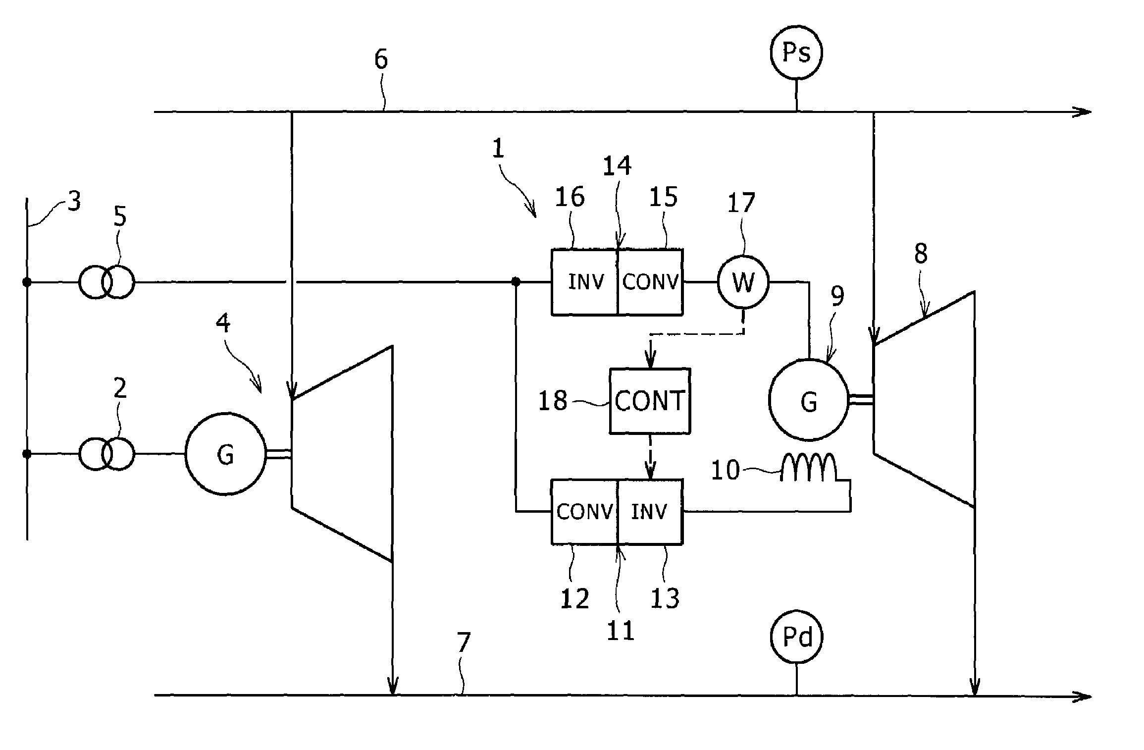
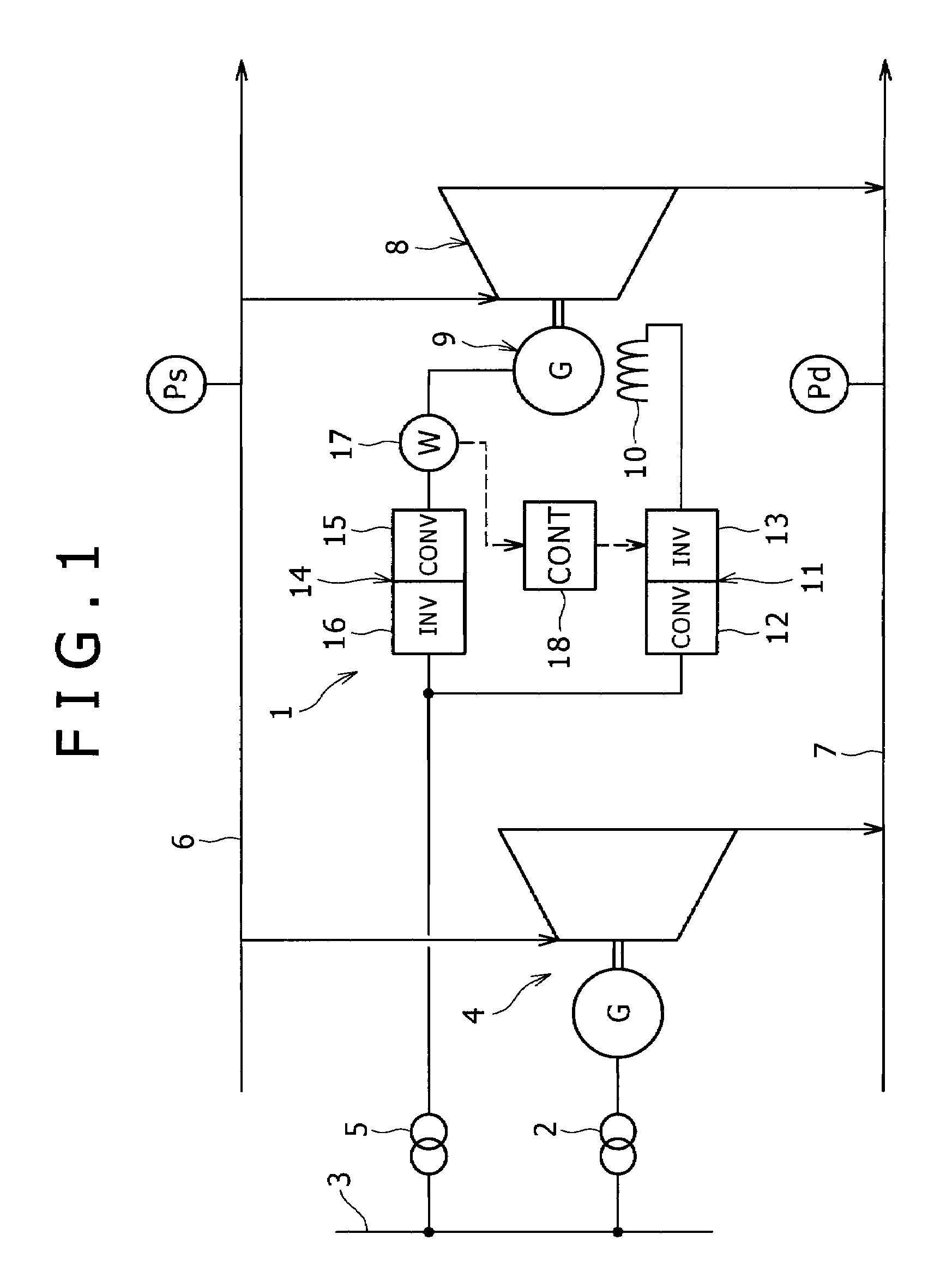
[0020]FIG. 1 shows a power generating system including a power generating device 1 according to the present invention. The power generating device 1 is supplementary power generating equipment which is installed in parallel to a main power generating device 4 with large capacity for supplying electric power to an electric power system 3 through an interconnecting transformer 2, and capable of supplying the electric power to the electric power system 3 through an interconnecting transformer 5.

[0021]High pressure steam of a predetermined pressure Ps (for example, 1.6 MPa) is supplied from a high pressure steam header 6 to the main power generating device 4. The main power generating device 4 converts energy of the high pressure steam into a rotational force so as to generate the electric power, and discharges the steam in which the energy is consumed and the pressure is decreased (for example, 0.1 to 0.8 MPa) to a low pressure steam header 7. Remaining energy of the low pressure steam...

second embodiment

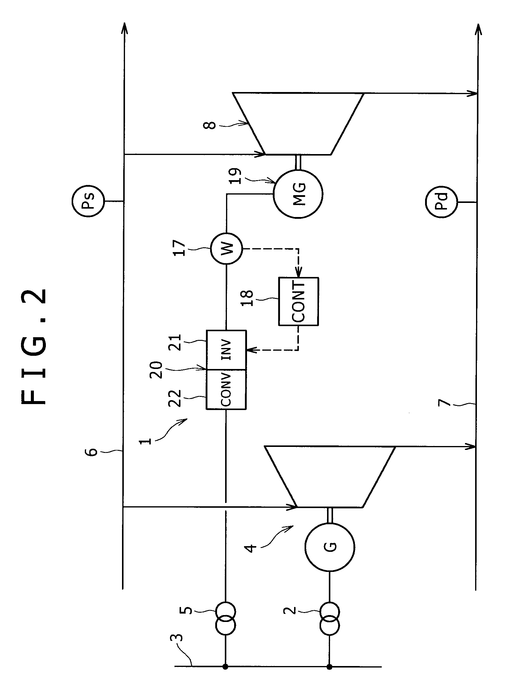
[0039]It should be noted that the present invention is not limited to the embodiments mentioned above. For example, instead of the output frequency converter 20 in the power generating device 1 according to the present invention, a matrix converter may be adopted. In comparison to the converter and the inverter for converting the alternating current to the direct current and then converting the direct current to the alternating current again, the matrix converter for directly converting the alternating current to the alternating current is advantageous in terms of small size, light weight and high efficiency.

[0040]The power generating device according to the present invention is not limited to the case where the power generating device is installed in parallel to a main power generating device with large capacity. The power generating device according to the present invention may be used alone.


PUM


Abstract

A power generating device according to the present invention has a positive displacement steam expander for converting expansion of steam into a rotational force, a power generator connected to a rotational axis of the positive displacement steam expander, an inverter for setting an operational frequency of the power generator, a power detector for detecting generated electric power of the power generator, and control means for changing set frequency of the inverter in accordance with a deviation of the generated electric power detected by the power detector from a target value. According to such a configuration, it is possible to sustain high output of the power generator irrespective of a differential pressure between primary side steam and secondary side steam.

Description

BACKGROUND OF THE INVENTION[0001]1. Field of the Invention[0002]The present invention relates to a power generating device.[0003]2. Description of the Related Art[0004]A power generating device for driving a power generator by rotating a turbine with steam is widely used. Secondarily utilizing low pressure steam discharged from the turbine is disclosed in Japanese Patent Laid-Open Nos. 2006-2576 and 2004-100657. In the power generating device in which the turbine is used, it is difficult to control pressure of the low pressure steam discharged from the turbine.[0005]A possibility of utilizing a positive displacement steam expander such as a screw expander is examined. The positive displacement steam expander has a flat characteristic that torque is determined on the basis of not a rotation speed but a difference between a supply pressure and a discharge pressure, and a flow rate of steam is proportional to the rotation speed.[0006]Output of the positive displacement steam expander i...

Claims


Application Information

Patent Timeline
Patent Type & Authority Patents(United States)
IPC IPC(8): F02D9/04
CPCF01K13/02H02P9/00H02J3/46
Inventor NAKAMURA, HAJIMEYOSHIMURA, SHOJINAKAMURA, MAKOTO
Owner KOBE STEEL LTD
Learn More