
Distributing frequency references

a frequency reference and frequency technology, applied in the field of frequency reference, can solve the problems of increasing cost and space, affecting and causing the accuracy of interval information to be deliberately overstated

Active Publication Date: 2009-09-15
KEYSIGHT TECH
View PDF10 Cites 51 Cited by
  • Summary
  • Abstract
  • Description
  • Claims
  • Application Information

AI Technical Summary

Problems solved by technology

This means each instrument requires yet another signal connector (typically a rear-panel BNC), which adds cost and takes up space.
Additional cabling between instruments can introduce ground loops and other undesirable signals which can make complex test and measurement environments even more complex.
The interval information may deliberately overstate its precision.

Method used


Image

  • Distributing frequency references
  • Distributing frequency references
  • Distributing frequency references

Examples


first embodiment

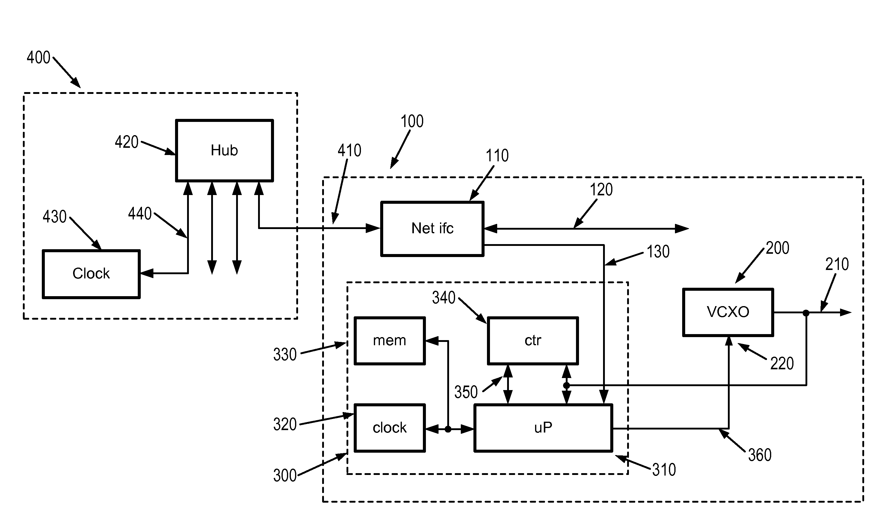
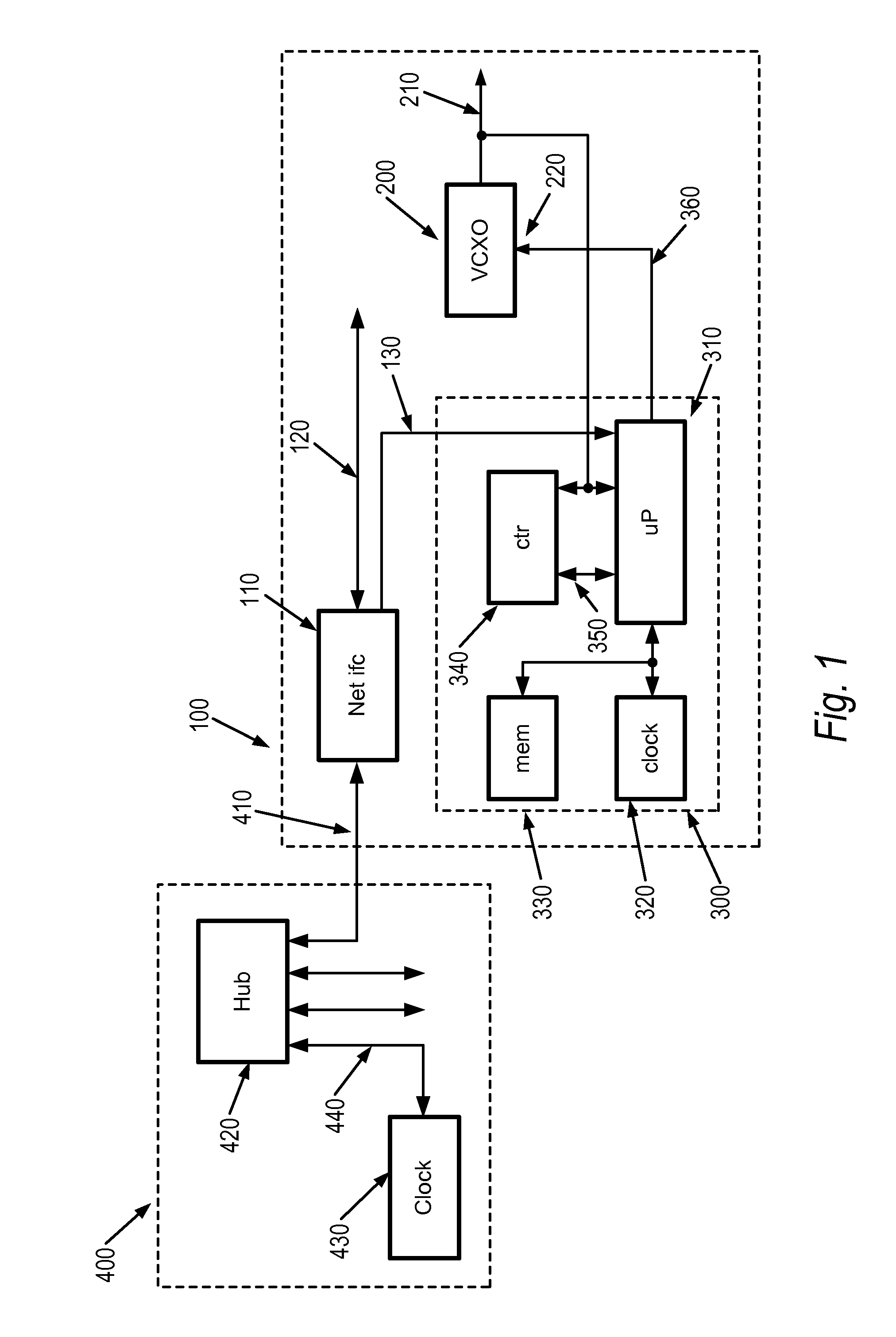
[0015]FIG. 1 shows a block diagram of a network aware oscillator according to the present invention. Network aware oscillator 100 connects 410 to network 400 through 1588-enabled network hub 420. Hub 420 may be any 1588-compliant hub, switch, or router; suitable switches and routers are available from companies such as Hirschmann Electronics and OnTime Networks. In the example shown, boundary clock 430 provides time synchronization services 440 according to the 1588 standard. OnTime Networks also produces 1588 boundary clocks, including GPS time synchronization.

[0016]Within network aware oscillator 100, network interface 110 provides network services 120 to clients within the instrument. Network interface 110 also provides, in coordination with 1588 messages, precision timing signal 130. For the present embodiment, precision timing signal 130 is in the nature of pulses at a predetermined interval, such as one pulse per second, or one pulse every two seconds. One such client is corre...

third embodiment

[0032]In the invention as shown in FIG. 4, an arbitrary frequency reference is distributed via a network to one or more instruments and used to correct references in those instruments. Arbitrary frequency reference 430 generates interval information 440 which is processed by IEEE-1588 aware network interface 420 and made available over network 410. The IEEE 1588 standard allows for devices to select a master based on accuracy information published in network messages for each source. For arbitrary source 430 to insure it is used as the master in a network, it may be desirable to deliberately overstate the published accuracy of reference 430.

[0033]Instruments 700, 710, and 720 connect to network 410. These instruments operate in accordance with the embodiments of the invention as shown in FIGS. 1 through 3 to match their reference oscillators to the performance of arbitrary reference 430. Thus, frequency errors, frequency drift, and the like in reference 430 will be tracked in the op...


PUM


Abstract

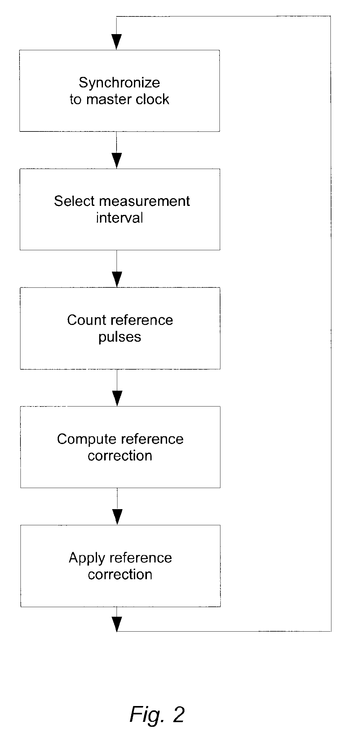
A correction processor connected to an oscillator uses precision timing signals propagated over a digital network to generate an error signal. IEEE-1588 time synchronization protocols produce precision time signals which are converted to precision interval signals. The correction processor uses the precision interval signals to count pulses of the oscillator. A correction circuit compares the counter output with a predetermined value and generates an error signal may be used to correct the oscillator or may be propagated to consumers of the oscillator. An arbitrary reference oscillator may be used to generate the precision timing signals propagated on the network, to slave other oscillators to it. The precision of the reference oscillator may be deliberately overstated to insure it is used as a master.

Description

TECHNICAL FIELD[0001]Embodiments in accordance with the invention are related to frequency references, and more particularly, to distributing frequency reference information among devices in a test or production environment, such as among test instruments, or between test instruments and a device under test.BACKGROUND[0002]Many laboratory and manufacturing test environments use a variety of electronic test and measurement equipment, including for example, signal generation and measurement instruments. In any situation where multiple instruments are used, the question of accuracy arises. If a signal generator is programmed to generate a signal at 146.115 MHz, and a frequency counter measures that frequency at 146115003.7 Hz, which instrument is more accurate? When the frequency counter reports 146115006.2 Hz a few hours later, which instrument has changed?[0003]Signal generation and measurement instruments generate and measure signals with respect to an internal oscillator, a referen...

Claims


Application Information

Patent Timeline
Patent Type & Authority Patents(United States)
IPC IPC(8): H03L7/06H03B5/32
CPCH04J3/0697H04J3/0667
Inventor CUTLER, ROBERT T.
Owner KEYSIGHT TECH
Learn More