Image sensing system for sensing an image and converting the image into image signals with a controlled operating rate

a sensing system and image technology, applied in the field of image sensing apparatus, can solve the problems of low image sensing rate, drop in image quality, and computer ay occasionally miss some image data

Inactive Publication Date: 2005-03-22
CANON KK
View PDF31 Cites 132 Cited by
  • Summary
  • Abstract
  • Description
  • Claims
  • Application Information

AI Technical Summary

Benefits of technology

The present invention has been made in consideration of aforesaid situation, and has as its object to provide an image sensing apparatus and system capable of sensing an image at the highest possible rate that a computer can receive image data from an image sensing unit without any loss of the data.

Problems solved by technology

Namely, although an image sensing rate is set to the rate at which a computer can receive all the image data when the computer is operated under a normal state, the computer ay occasionally miss some image data because of interruption by other processes during receiving the image data.
However, the low image sensing rate causes a drop of image quality because of greater movement of an object to be sensed during sensing it and an increase of dark current noises.
Now, since the resolution of a liquid crystal display of a computer is generally low, the number of reproducible color of the display is often limited.
However, there are following problems, especially in luminous exposure control, in the aforesaid conventional image sensing device.
(1) If a mechanical iris diaphragm meter or a motor is mounted, the size and the weight of the camera increases as well as energy consumption increases.
This is fatal to a digital camera which is supplied with electrical power from a computer.
Accordingly, it is not practical to adjust luminous exposure by controlling the exposure time.
It is possible to widen an adjustable range of luminous exposure by providing a couple of fixed iris diaphragms and switching between them, however, it is still not enough.
Furthermore, for sensing a low luminance object, since the exposure time can be extended up to only 1 / 60 second, the lowest luminosity that the camera can sense is not low enough.
This is fatal since it is difficult to sense an image inside of a building.
(3) Gains set in an amplifier for amplifying output signals from the image sensing device may be increased by 6 dB˜18 dB when sensing a low luminance object, however, the S / N ratio increases, thus an obtained image would not be good.

Method used


Image

  • Image sensing system for sensing an image and converting the image into image signals with a controlled operating rate
  • Image sensing system for sensing an image and converting the image into image signals with a controlled operating rate
  • Image sensing system for sensing an image and converting the image into image signals with a controlled operating rate

Examples


first embodiment

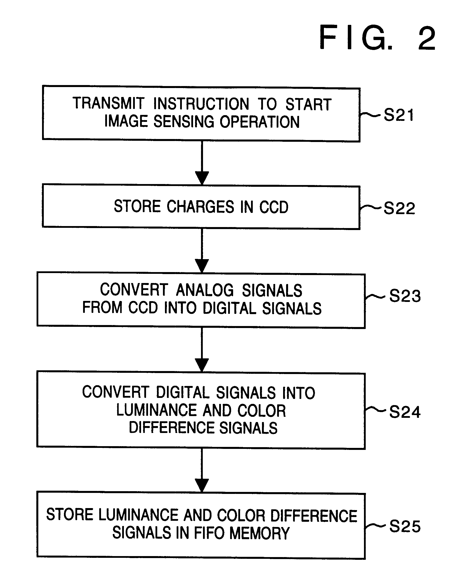
[Adjusting Operating Rate of an Image Sensing Device]

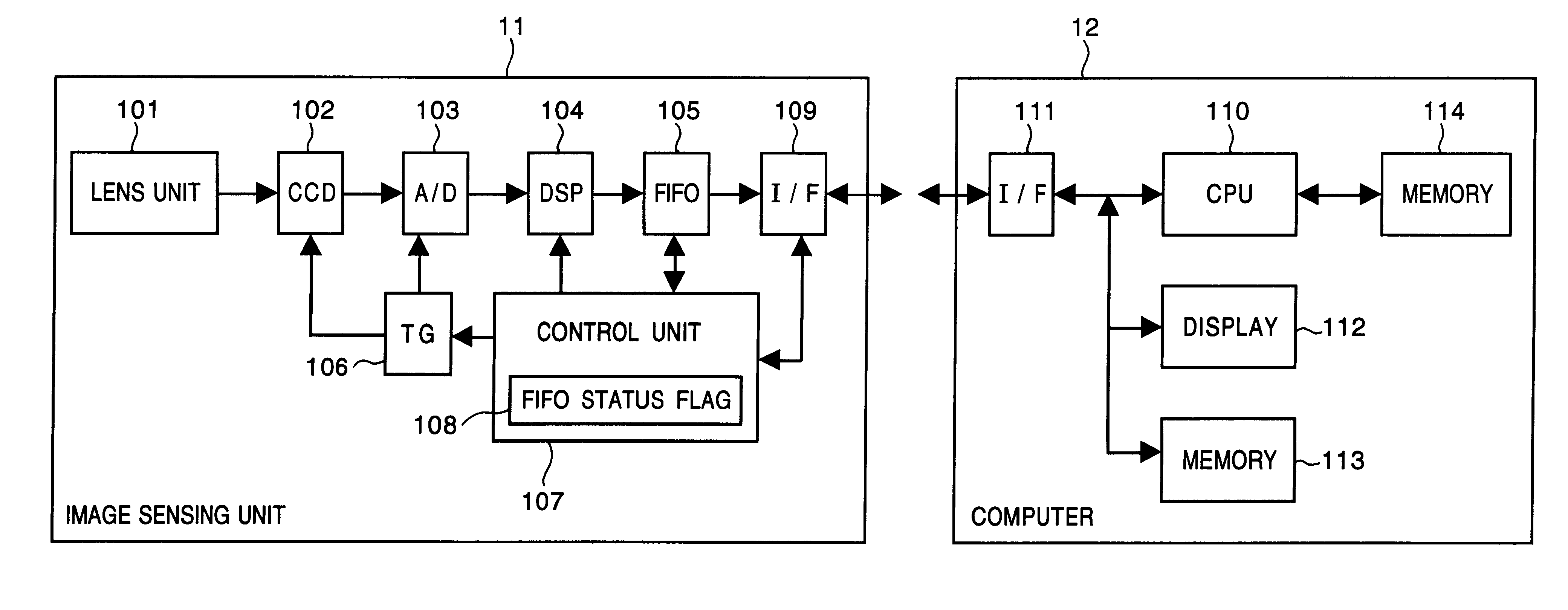
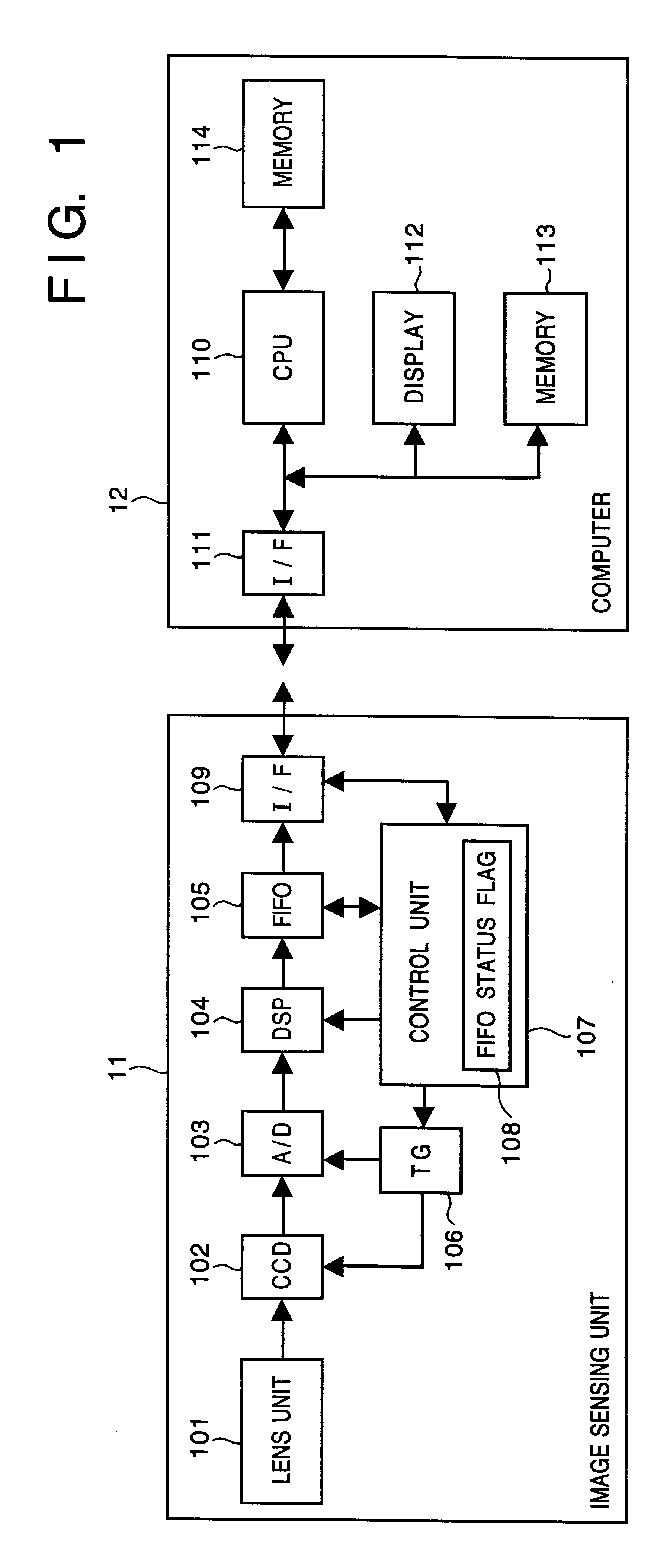
FIG. 1 is a block diagram illustrating a configuration of an image sensing system according to the first embodiment, and in the image sensing system, an image sensing unit 11 is connected to a computer 12 to perform image sensing operation.

In the image sensing unit 11, reference numeral 101 denotes a lens unit; 102, a CCD; 103, an analog-digital (A / D) converter; 104, a digital signal processor (DSP); and 105, a FIFO memory. Further, reference numeral 106 denotes a timing signal generator (TG) for outputting timing pulses to the CCD 102 and the A / D converter 103. Reference numeral 107 denotes a control unit for the image sensing unit 11 and maintains a FIFO status flag 108 of the FIFO memory 105. Reference numeral 109 denotes an interface (I / F), such as the one conforming to the PCMCIA standard, for connecting to an external device.

In the computer 12, reference numeral 110 denotes a CPU; 111, an interface, such as the one conformin...

second embodiment

FIG. 9 is a block diagram illustrating an internal configuration of an image sensing unit, such as a digital camera, to be connected to a computer according to the second embodiment, and the same reference numerals as those in FIG. 11 denote the same units and elements.

In FIG. 9, reference numeral 1 denotes an optical lens for forming an optical image of an object; 2, an iris diaphragm whose aperture is fixed; 3, an image sensing device for converting the optical image of the object into electric signals; 4, a timing generator (TG) for generating timing signals necessary for operating the image sensing device 3; and 10, an image signal processing circuit which is a digital processing circuit.

Further, reference numeral 5 denotes an image sensing device operating unit; 6, a correlated double sampling (CDS) circuit for removing noises; 8, a clumping circuit for fixing black level; 9, an analog-digital (A / D) converter for converting analog signals to digital signals; 10, the image signa...

embodiment

Further, the object of the present invention can be also achieved by providing a storage medium storing program codes for performing the aforesaid processes to a system or an apparatus, reading the program codes with a computer (e.g., CPU, MPU) of the system or apparatus from the storage medium, then executing the program.

In this case, the program codes read from the storage medium realize the functions according to the embodiments, and the storage medium storing the program codes constitutes the invention.

Further, the storage medium, such as a floppy disk, a hard disk, an optical disk, a magneto-optical disk, CD-ROM, CD-R, a magnetic tape, a non-volatile type memory card, and ROM can be used for providing the program codes.

Furthermore, besides aforesaid functions according to the above embodiments are realized by executing the program codes which are read by a computer, the present invention includes a case where an OS (operating system) or the like working on the computer performs...


PUM


Abstract

In an image sensing apparatus using an image sensing device, such as a CCD, to be used by connecting to an external device, such as a computer, an operating rate of the CCD is changed in accordance with a rate at which the computer receives image signals from the image sensing apparatus. Further, when the operating rate of the CCD is changed, a proper exposure value is conjectured to obtain an image sensed at a proper exposure on the basis of operating rates of the CCD before and after the operating rate is changed, and a proper exposure value of the CCD before the operating rate is changed.

Description

BACKGROUND OF THE INVENTIONThe present invention relates to an image sensing apparatus used with a computer and an image sensing system comprising an image sensing unit and a computer.When a computer has a connector of the Personal Computer Memory Card International Association (PCMCIA) standard, it is common to use the computer with many kinds of card units, also having a PCMCIA standard connector, of a variety of functions, such as a facsimile card and a memory card, by connecting them to the computer. In other words, it is possible to use a card having a PCMCIA standard connector by connecting it to many kinds of computers having connectors of the PCMCIA standard.Since it is possible to transmit data at high rate through connectors of the PCMCIA standard, it is effective to use them as an input means to a computer to input an image which is generally represented by a large amount of data.FIG. 10 is an overall view of a conventional image sensing system consisting of an image sens...

Claims


Application Information

Patent Timeline
Patent Type & Authority Patents(United States)
IPC IPC(8): G06F3/00H04N5/235H04N5/232
CPCG06F1/1632H04N5/2352H04N5/232H04N23/661H04N23/633H04N23/72
Inventor KOIDE, YUJIKONDO, KENICHIFUKUSHIMA, NOBUOSEKINE, MASAYOSHISONO, KOICHIWATANABE, GAKU
Owner CANON KK
Why Eureka
Try Eureka