
Methods and apparatuses for external delay test of input-output circuits

a delay test and input-output technology, applied in the field of self-testing and repair of input-output circuits (ios), can solve the problem of increasing the cost of i-o testing with a

Active Publication Date: 2009-09-15
SYNOPSYS INC
View PDF129 Cites 22 Cited by
  • Summary
  • Abstract
  • Description
  • Claims
  • Application Information

AI Technical Summary

Problems solved by technology

I-Os, like all other circuits on the chip, are subject to random defects and statistical process variations, which may render them faulty.
However, almost all types of I-O are tested for DC parameters because such tests reveal a significant portion of faults very quickly.
Although flexible and fast, the use of ATE for I-O test is becoming increasingly expensive because of large tester pin requirements.

Method used


Image

  • Methods and apparatuses for external delay test of input-output circuits
  • Methods and apparatuses for external delay test of input-output circuits
  • Methods and apparatuses for external delay test of input-output circuits

Examples


Embodiment Construction

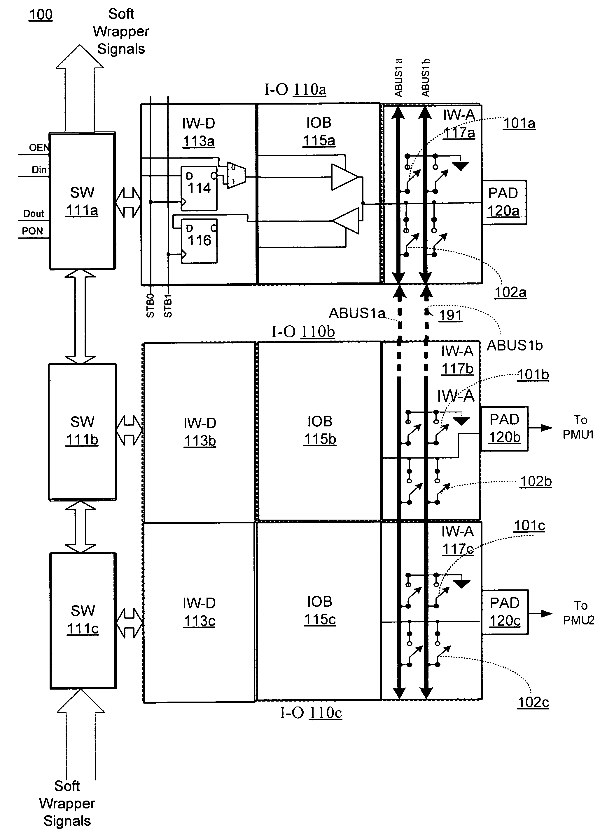
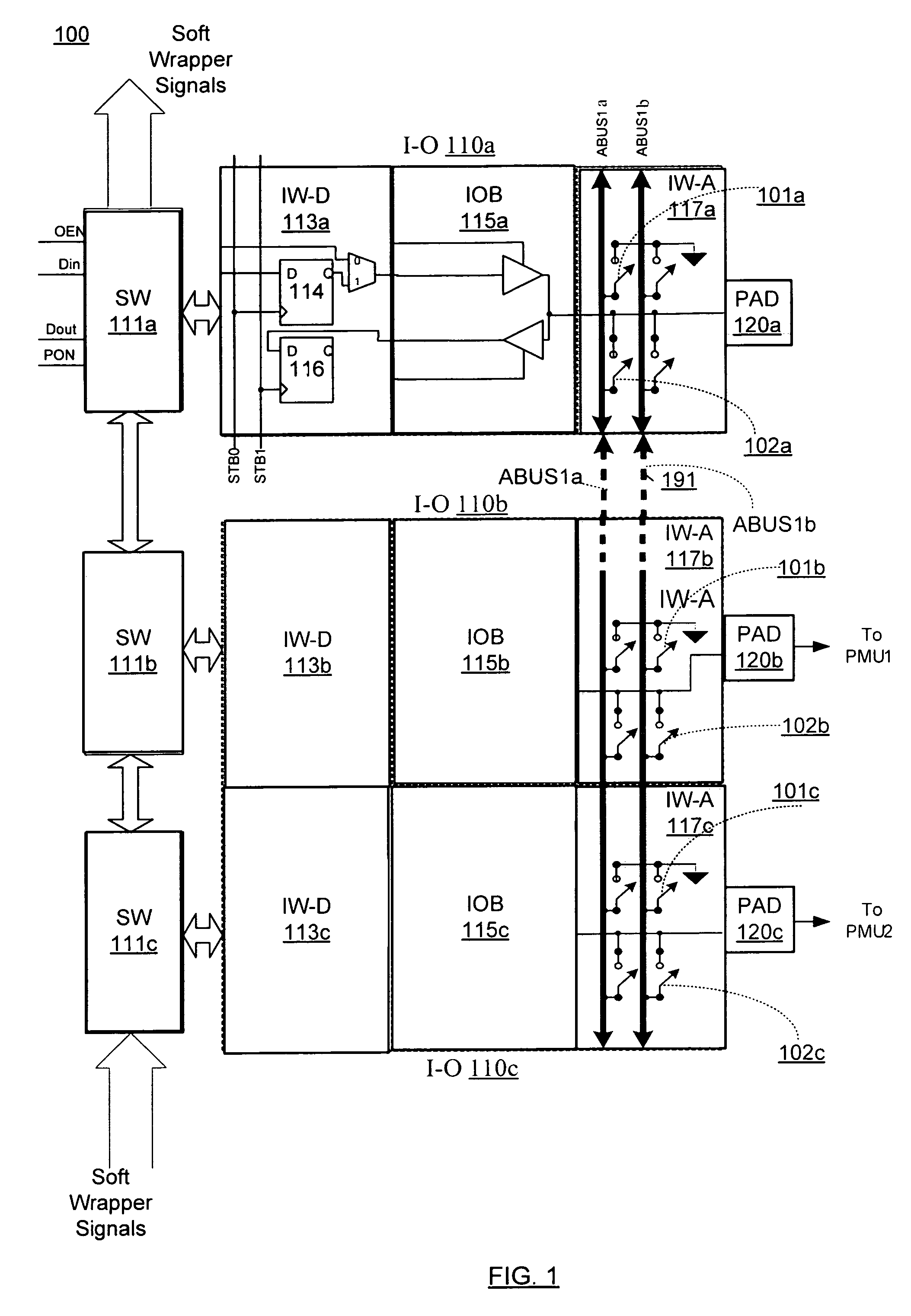
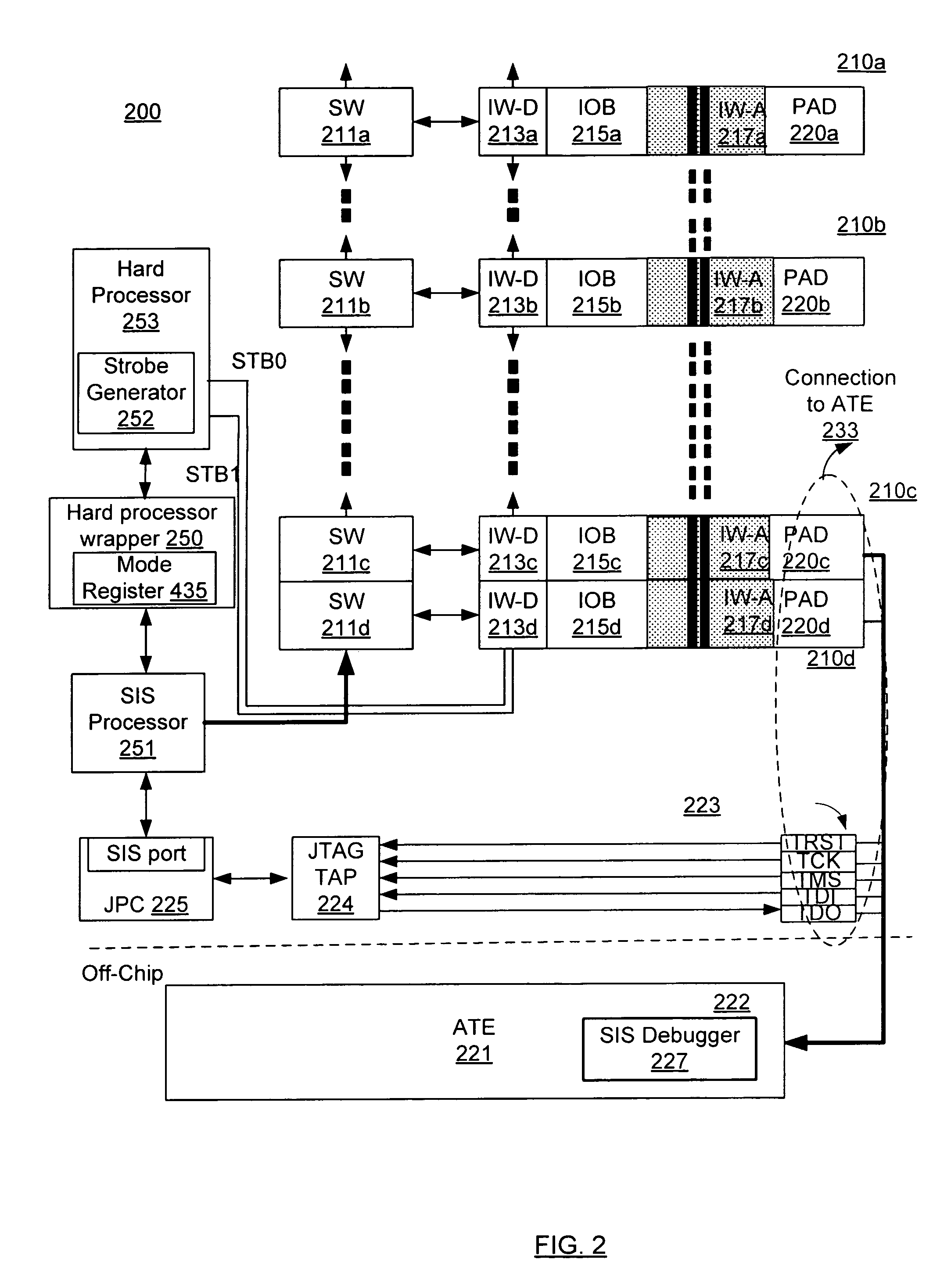
[0024]In the following description, numerous specific details are set forth, such as examples of specific data signals, named components, connections, etc., in order to provide a thorough understanding of the embodiments of the invention. It will be apparent, however, to one of ordinary skill in the art that the embodiments of the invention may be practiced without these specific details. However, the specific numeric references should not be interpreted as a literal sequential order but rather interpreted as a first group of I-Os being different from a second group of I-Os. Thus, the specific details set forth are merely exemplary. The specific details may be varied from and still be contemplated to be within the spirit and scope of the claims.

[0025]In general, various methods and apparatuses are described for a system that includes some on-chip components, e.g., I-Os, test processors, soft wrappers, etc., an external testing unit that provides Parametric Measurement Unit (PMU) cap...


PUM


Abstract

Various methods and apparatuses are described for a system that includes some on-chip components, e.g., I-Os, test processors, soft wrappers, etc., an external testing unit that provides Parametric Measurement Unit (PMU) capability, and various tests performed on the I-Os by the on-chip testing logic, the test vector patterns supplied by the external testing unit.

Description

RELATED APPLICATIONS[0001]This application claims priority to U.S. Provisional Patent Application No. 60 / 716,386, entitled VARI-OUS METHODS AND APPARATUSES FOR INPUT-OUTPUT DESIGNS, filed on Sep. 12, 2005.FIELD OF THE INVENTION[0002]Aspects of embodiments of the invention generally relate to the field of self test and repair for Input-Output circuits (I-Os). More specifically, an embodiment of the invention provides Direct Current (DC) test features for I-Os.BACKGROUND OF THE INVENTION[0003]Any integrated circuit (IC) device typically includes a number of input / output (I-O) circuitry to communicate information with the outside world. Different types of I-Os may be used in a chip that supports different signal voltage levels, current drives, data protocol, and data rates. I-Os, like all other circuits on the chip, are subject to random defects and statistical process variations, which may render them faulty. Consequently, the I-O circuits are tested to ensure they meet their advertis...

Claims


Application Information

Patent Timeline
Patent Type & Authority Patents(United States)
IPC IPC(8): G01R31/28
CPCG01R31/318572G01R31/318508
Inventor TABATABAEI, SASSANZORIAN, YERVANT
Owner SYNOPSYS INC
Learn More