Flow sensor and mass flow controller using the same

a flow sensor and controller technology, applied in the direction of volume metering, process and machine control, instruments, etc., can solve the problems of increasing the cost of producing the bypass assembly, difficulty in achieving a size reduction, and increasing the cost, so as to improve the rectifying effect of the fluid flowing through the bypass passage, reduce the length of the bypass passage, and compact the effect of siz

Active Publication Date: 2009-09-22
HITACHI METALS LTD
View PDF7 Cites 6 Cited by
  • Summary
  • Abstract
  • Description
  • Claims
  • Application Information

AI Technical Summary

Benefits of technology

[0016]The present invention has been accomplished in view of the above problems, and it is an object of the invention to provide a low cost, compact, high performance flow sensor that can be small in size even when used for a large flow rate and to provide a mass flow controller using the same.
[0024]In the above configuration, the bypass passage includes a plurality of fine flow passages satisfying Equation 4. In this manner, a rectifying effect on the fluid flowing through the bypass passage is improved, and the length of the bypass passage can thereby be reduced. Therefore, the flow sensor can be made compact in size. In addition, a mass flow controller using the above flow sensor can be made compact in size even when used for a large flow rate and can be manufactured at low cost.
[0026]With the flow sensor of the present invention and the mass flow controller using the same, the following effects can be obtained.
[0027]Since the bypass passage includes a plurality of fine flow passages satisfying Equation 4, the rectifying effect on the fluid flowing through the bypass passage is improved, and the length of the bypass passage can thereby be reduced. Therefore, the flow sensor can be made compact in size. In addition, the mass flow controller using the above flow sensor can be made compact in size even when used for a large flow rate and can be manufactured at low cost.

Problems solved by technology

Disadvantageously, as the number of fine tubes increases, the size of the flow sensor will also increase, thus undesirably increasing the cost of producing the bypass assembly.
As a result, it is difficult to achieve a size reduction.
Therefore a different corrugated plate must be used for a different flow rate range, and this results in an increase in cost.
As a result, the size of the mass flow controller increases.

Method used


Image

  • Flow sensor and mass flow controller using the same
  • Flow sensor and mass flow controller using the same
  • Flow sensor and mass flow controller using the same

Examples


examples

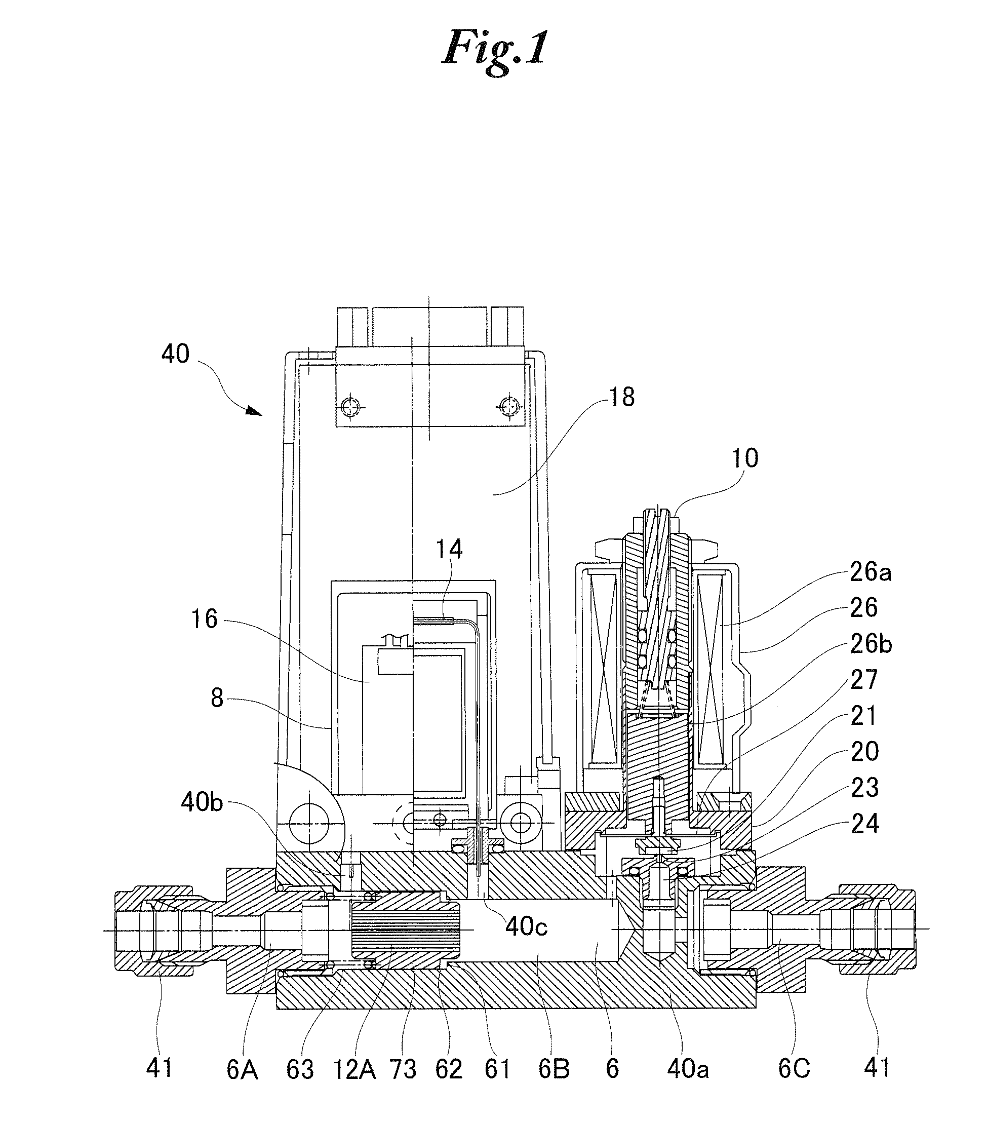
[0053]The bypass assemblies 12A shown in FIG. 2(a) and a bypass assembly 12C shown in FIG. 2(b) were installed in mass flow controllers 40, respectively. As shown in FIG. 4, a pressure control valve 80, the mass flow controller 40, and a mass flow meter 81 calibrated in advance were disposed in series. While a gas at a constant pressure was supplied from the upstream side at a maximum flow rate of 10 SLM, a linearity during each mass flow control was determined for each mass flow controller 40, and the results were compared.

[0054]Nitrogen gas of 0.05 MPa was used as a processing gas, and a mass flow rate QSP was measured using the mass flow meter 81 when a flow setting signal SP sent to the mass flow controller 40 was sequentially changed from 20% of a maximum flow rate (full scale flow rate) QFS to 100% of the maximum flow rate QFS.

[0055]The graphs shown in FIGS. 5(a) to 5(e) compare the linearity relationships between the flow rates and the flow rate signals in several Examples an...


PUM


Abstract

A low cost, compact, high performance flow sensor that can be made small in size even for use in a large flow rate and a mass flow controller using the same are provided. The flow sensor includes a bypass passage, a sensor passage, and a bridge circuit including heat-generating resistance wires that constitute a part of the bridge circuit and are wound around the sensor passage. The flow sensor determines a total flow rate of a fluid that flows in a branched manner through the bypass passage and the sensor passage at a predetermined flow ratio. The total flow rate is determined by detecting, as an unbalance of the bridge circuit, heat transfer caused by the fluid flowing through the sensor passage and is outputted as a sensor output of the flow sensor. In the flow sensor, the bypass passage includes a plurality of fine flow passages each having a cross-section defined by a substantially linear edge and a curve in contact with the substantially linear edge. The ratio of the equivalent hydraulic diameter (d) of the fine flow passages to the common logarithm of the length (T) of the fine flow passages is 0.27 or less. The flow sensor is installed in the mass flow controller.

Description

BACKGROUND OF THE INVENTION[0001]The present invention relates to a flow sensor for measuring the mass flow rate of a fluid such as a gas flowing at a relatively small flow rate, and to a mass flow controller using the same.[0002]Generally, to manufacture semiconductor products such as semiconductor integrated circuits, CVD and etching processes, for example, are repeatedly performed on semiconductor wafers using various semiconductor manufacturing device. In such cases, mass flow controllers are used because of the need to accurately control the feed rate of processing gas used in a small amount.[0003]Next, the configuration of a general mass flow controller is described with reference of FIGS. 6 and 7. FIG. 6 is a schematic configuration diagram of an example of a conventional mass flow controller interposed in gas tubing, and FIG. 7 is a circuit diagram of a flow sensor of the mass flow controller.[0004]As shown in the figures, the mass flow controller 2 is interposed in a passag...

Claims


Application Information

Patent Timeline
Patent Type & Authority Patents(United States)
IPC IPC(8): G01F1/68
CPCG01F1/6847G05D7/0635G01F5/00G01F1/60G01F1/68G01F15/00
Inventor SUGIMOTO, MASATOHAYASHI, AKIFUMI
Owner HITACHI METALS LTD
Why Eureka
Try Eureka