Method and apparatus for driving a DC motor

a dc motor and control method technology, applied in the direction of dynamo-electric machines, synchronous motor starters, stopper details, etc., can solve the problems of inapplicability of back emf sensing approach, inability to use the vast majority of single-phase brushless dc motors, and inability to have natural single-phase motors

Active Publication Date: 2009-09-22
AMI SEMICON BELGIUM
View PDF2 Cites 8 Cited by
  • Summary
  • Abstract
  • Description
  • Claims
  • Application Information

AI Technical Summary

Benefits of technology

[0030]The electric motor comprises a stator and a rotor, one or more set of windings and presents accidental or intentional asymmetry and / or eccentricity (e.g. dissymmetry or deformation of the permanent rotor magnet, deformed stator or mechanical dissymmetry between stator and rotor) that influences the variation of the back electromotive force induced in said windings in function of the angular position of the rotor with respect to the stator. The motor can be a single phase brushless DC motor with a tapered air-gap as seen on FIG. 11. The stator windings (111) (112) are wound around pole shoes (113) (114). The rotor (115) comprises a permanent magnet. The angular position of the rotor (115) is the angle θ (118) between an axis of reference (117) that is fixed with respect to the stator (116) and the North-South axis (119) of the stator magnet. The axis of reference (117) is chosen so that θ is equal to 0 (or an integer multiple of II) when the North-South axis of the rotor permanent magnet is aligned with the magnetic field generated by the stator windings. As seen on FIG. 11, the air gap between the rotor (115) and the pole shoes (113) and (114) is tapered. The tapered air gap may be intentional or accidental. The tapered air gap introduces an asymmetry in the distribution of the induction field lines and / or the local amplitude of the magnetic field that may help solve the “dead point” problem that was briefly discussed earlier. The asymmetry of the amplitude of the BEMF signal resulting from e.g. a tapered air gap may be defined in mathematical terms as follows: the BEMF signal will be said to be asymmetric if the graph of the amplitude of the BEMF signal in function of the angular position θ of the rotor is not symmetrical (even at constant speed of rotation) with respect to an axis θ=k*π (with k being an integer number). For instance, one sees on FIG. 10A that the graph of the amplitude of the BEMF signal in function of the angular position of the rotor is not symmetrical with respect to the axis θ=π. On the other hand, if the segments BC and B′C′ had been parallel with the axis Theta (i.e. θ), the graph would have been symmetrical with respect to the axis θ=π.

Problems solved by technology

Single phase motors do not have natural intervals when one phase is open circuited where the phase current remains zero for any length of time and the back EMF sensing approach is therefore not applicable.
The solution proposed in U.S. Pat. No. 5,986,419 requires that the motor be fabricated or modified to accommodate an extra winding and therefore that solution cannot be used with the vast majority of single phase brushless DC motors.
Furthermore, the proposed method does not allow determination of the sense of rotation of the motor, a rather important parameter.
Time sharing of the stator windings may however be a disadvantage and even become impossible when for instance access to the BEMF signal is desired at times when the stator windings are required for driving (b).
The estimation of the bemf will depend on the availability of the characteristics of the motor and / or the precision with which these characteristics are known (these characteristics may vary from one motor to another in a system destined to mass market commercialization) and therefore, estimation of the bemf signal is not always possible.

Method used


Image

  • Method and apparatus for driving a DC motor
  • Method and apparatus for driving a DC motor
  • Method and apparatus for driving a DC motor

Examples


Embodiment Construction

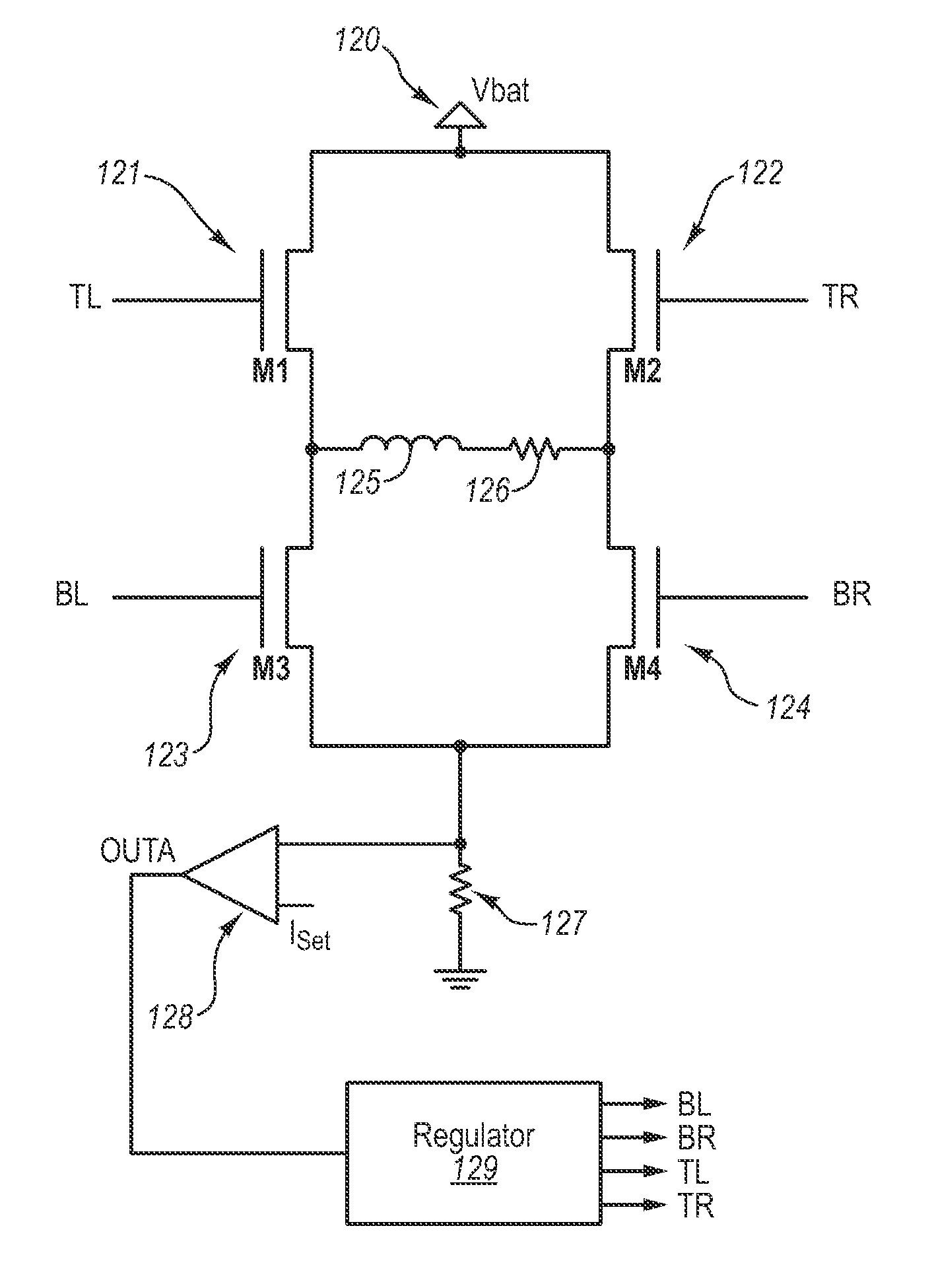
[0060]In the following, the acronym BEMF will designate the back electromotive force. Together with BEMF either back emf or BEMF signal will be used to refer to the back electromotive force signal. The following convention will be used when describing the state of a switch and in particular transistor switch. The transistor (switch) will be said to be closed (as if it were a normal mechanical switch) when it allows current to flow through it. In other words, when the transistor switch is closed it is conducting. The transistor (switch) is then switched ON. The transistor (switch) will be said to be opened when it does not allow current to flow through it. In other words, when the transistor switch is opened it is not conducting. The transistor (switch) is then said to be switched OFF.

[0061]Driving a permanent magnet brushless motor usually requires a knowledge of the BEMF signal (and / or characteristics of the back electromotive force signal) and in particular the moments at which th...


PUM


Abstract

A circuit for determining a direction of rotation of an electric motor, the motor having asymmetry and / or eccentricity in a profile of back electromotive force as a function of angular position of a rotor with respect to a stator, the circuit receiving a signal representing the BEMF, and use the corresponding asymmetry and / or eccentricity in the signal to derive the direction of rotation. The signal representing the back emf can be generated by a control circuit. The control circuit can have a feedback loop regulator to generate a control signal (TL or TR) to control a current drive circuit (11,12) to control an amplitude of current (iw) in the windings, the feedback loop regulator being arranged to compare the amplitude of the current (iw) in the windings with a reference value (iset), and use the control signal to provide the signal representing the back electromotive force.

Description

CROSS-REFERENCE TO RELATED APPLICATIONS[0001]This patent application claims the benefit of British Patent Application Serial No. 0700033.4, filed Jan. 2, 2007, which patent application is incorporated herein by reference in its entirety.FIELD OF THE INVENTION[0002]The present invention relates in general to the control of a brushless DC motor and in particular to a method and an apparatus to control a brushless DC motor without position sensor e,g. hall sensor or optical encoder and determine the direction of rotation of the motor.DESCRIPTION OF THE RELATED ART[0003]It is known to the art how to determine the position of the rotor of permanent magnet motors and control those motors without a Hall sensor or any other position sensor. Such control schemes that do not require a position sensor are referred to as sensorless control schemes. A number of these sensorless control schemes rely on the back electromotive force (BEMF or back EMF). During operation of the motor, the windings se...

Claims


Application Information

Patent Timeline
Patent Type & Authority Patents(United States)
IPC IPC(8): H02P3/00
CPCH02P6/002H02P6/18H02P6/085H02P2209/07H02P6/182H02P6/28H02P6/30
Inventor VERMEIR, SAMLAULANET, FRANCOISDECOCK, BART
Owner AMI SEMICON BELGIUM
Why Eureka
Try Eureka