Wavefront sensor

a sensor and wavefront technology, applied in the field of wavefront sensors, can solve the problems of reducing the measurement range of the device, reducing the sensitivity of the device, and a defect in the telescope optics

Active Publication Date: 2009-09-29
ALCON INC
View PDF6 Cites 27 Cited by
  • Summary
  • Abstract
  • Description
  • Claims
  • Application Information

AI Technical Summary

Benefits of technology

[0017]The present invention is directed to an apparatus comprising two screens, each having a two-dimensional array of circular apertures, wherein the second screen is rotated with respect to the first screen, thereby creating a Moiré effect.

Problems solved by technology

If there was any deviation in the location of the holes of the Hartmann screen observed in the image of the Hartmann screen created by the telescope optics, then a defect was present in the telescope optics.
Such a small shift can be difficult to detect and measure.
However, this increase in sensitivity comes at the price of reducing the range of measurement of the device.
Increased sensitivity comes at the expense of range, and increased range comes at the expense of sensitivity in these devices.
A review of the literature in the public domain will yield many examples of such efforts, but all of these efforts require that the system be made more complex with such things as moving optical parts, higher resolution, more expensive cameras, complex sub-pixel analysis, etc.
This allows Hartmann-based optics to examine beams of light in multiple wavelengths if necessary, which is particularly useful when measuring the human eye, whereas Talbot based optics are limited to function in narrower wavelength bands of light.
CCD cameras have square pixels aligned in rows and columns, causing aliasing distortions when the shadow lines formed by Talbot optics that utilize rulings or gratings align with the rows of pixels, which interferes with the analysis.

Method used


Image

  • Wavefront sensor
  • Wavefront sensor
  • Wavefront sensor

Examples


example 1

Testing the Wavefront Sensor with Spherical and Cylindrical Trial Lenses

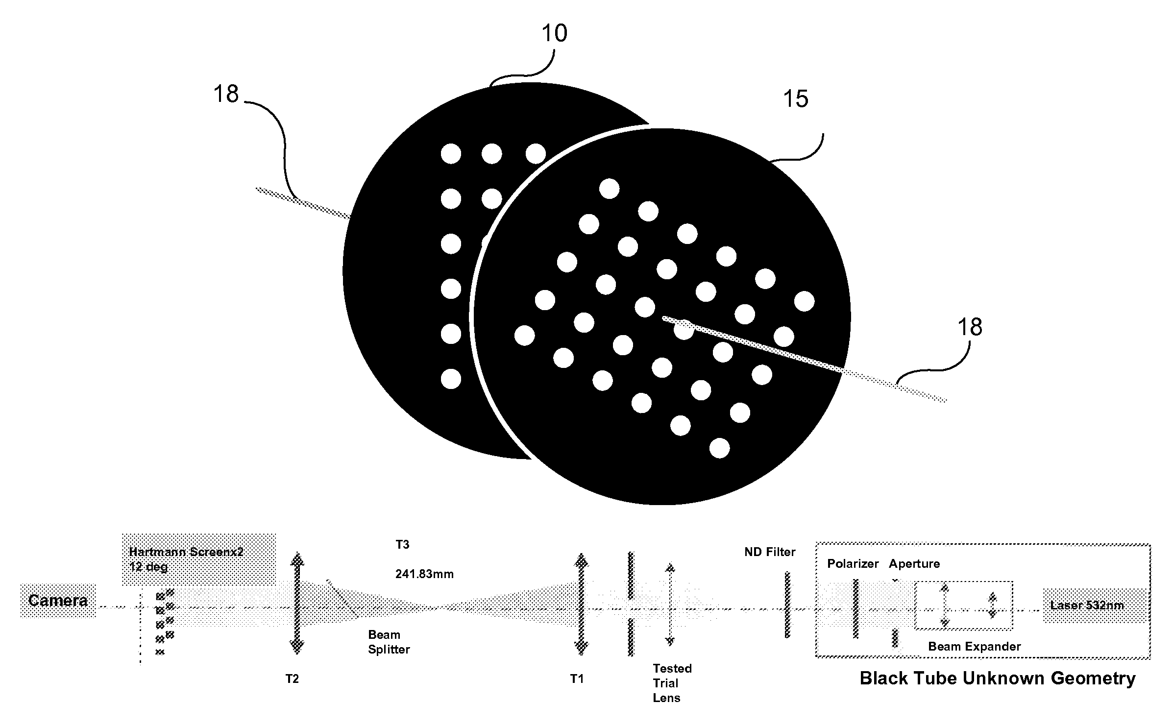
[0085]Data were measured at a wavelength of 532 nm without focus adjustment so that the full range of wavefront vergences was presented to the wavefront sensor. The accuracy and dynamic range of the Hartmann-Moiré wavefront sensor was evaluated by measuring defocus and astigmatism induced by a series of standard Topcon spherical lenses (e.g., 77 lenses from −20 D to +18 D) and cylindrical trial lenses (e.g., 16 lenses from −8 D to 8 D). Repeatability of the Hartmann-Moiré instrument was assessed by taking 3 repeated measurements within a 2-minute period. Measured trial lens values with the Hartmann-Moiré wavefront sensor were compared to lens values verified with a standard lensometer. Analyses were based on a 4-mm pupil diameter specified in the software. The test configuration is shown in FIG. 22.

[0086]Measurements should be taken to assure tight alignment tolerance (decentration tilt). For example, for accura...

example 2

Comparison of Hartmann-Moiré to Talbot-Moiré

[0092]FIGS. 32-35 demonstrate the improved image quality achieved by the Hartmann-Moiré wavefront sensor described herein as compared with a Talbot-Moiré wavefront sensor. FIGS. 32 and 34 show CCD camera photographs of the shadow patterns created by a Talbot-Moiré wavefront sensor. FIGS. 33 and 35 show CCD camera photographs of the spot patterns created by a Hartmann-Moiré wavefront sensor configured to produce similar sized spots as the shadows depicted in FIGS. 32 and 34, respectively.

[0093]As shown by the comparative figures, the spots formed by the Hartmann-Moiré wavefront sensor are of a high image quality, allowing for a more accurate determination of each spot's center and a more accurate measurement of the spot's movement and position.

example 3

Comparative Examples for Measuring a Model Eye

[0094]FIG. 36 shows two images from a comparative Shack-Hartmann device. FIG. 36A shows spots of light formed when a plane wave is being measured (i.e., an emmetropic eye), and FIG. 36B shows spots of light formed when the model eye has a converging beam of light emerging from it (i.e., a myopic eye). As the beam of converging light passes through the Shack-Hartmann device, the spots grow closer together, and the amount that they have moved is easily observed. However, at the relatively low optical power of only four Diopters, the spots of light begin to lose their contrast and become blurry. This makes the task of determining the centroid of the spot of light difficult, if not impossible. As the power of the converging light grows beyond four Diopters, the spots of light will get even more blurry, to the point of where the device can no longer make a measurement, which is why this device has a low dynamic range.

[0095]FIG. 37 shows two i...


PUM


Abstract

The present invention relates to a wavefront sensor using a pair of screens, each having a two-dimensional array of circular apertures, to achieve Moiré effects, and its use to measure the slope of a wavefront.

Description

CROSS-REFERENCES TO RELATED APPLICATIONS[0001]This application claims the benefit of U.S. Provisional Patent Application No. 61 / 001,042 filed Oct. 31, 2007, which is incorporated herein by reference.BACKGROUND OF THE INVENTION[0002]A wavefront sensor is a device for measuring the aberrations of an optical wavefront. Hartmann developed the Hartmann Test over one hundred years ago, yet the Hartmann class of wavefront sensors continues to be the most commonly used type of wavefront sensors to this time.[0003]The first Hartmann Test was simply a screen, a sheet of material with a series of holes cut into it. The Hartmann screen was placed at the opening of a telescope and then viewed with the telescope's optics, either lenses or mirrors. If there was any deviation in the location of the holes of the Hartmann screen observed in the image of the Hartmann screen created by the telescope optics, then a defect was present in the telescope optics. In other words, aberrations were present in t...

Claims


Application Information

Patent Timeline
Patent Type & Authority Patents(United States)
IPC IPC(8): A61B3/10
CPCA61B3/1015G01M11/0264G01J9/00G01J2009/002
Inventor VAN HEUGTEN, ANTHONY Y.
Owner ALCON INC
Why Eureka
Try Eureka