Wavelength division multiplexing optical transmission system and transmission wavelength control method therefor

a transmission system and wavelength control technology, applied in the field of wavelength division multiplexing optical transmission system, can solve the problems of large amount of time and work required for such setting and wiring, delay in normal operation, incorrect setting, etc., and achieve the effect of reducing the workload of optical transmitters, avoiding the occurrence of incorrect setting, and reducing the cos

Inactive Publication Date: 2009-09-29
FUJITSU LTD
View PDF14 Cites 16 Cited by
  • Summary
  • Abstract
  • Description
  • Claims
  • Application Information

AI Technical Summary

Benefits of technology

[0013]Accordingly, it is an object of the present invention to provide a wavelength multiplexing optical transmission system and a transmission wavelength control method therefor, thereby enabling easy setting of the transmission wavelengths in an optical transmitter in the wavelength multiplexing optical transmission system, and a reduced workload therefor.
[0020]In the wavelength division multiplexing optical transmission system according to the present invention, when setting the transmission wavelengths of the wavelength-variable optical transmitter in case of addition or expansion of the optical transmitter, each transmission wavelength is set automatically so as to match with each port wavelength of the input port in the multiplexer. Therefore, the setting workload of the optical transmitter is remarkably reduced, and occurrence of incorrect setting can be avoided. Also, with a simple and low-cost structure, the cost is restrained from increasing.

Problems solved by technology

Therefore, a vast amount of time and work are necessary for such setting and wiring at the time of installation and expansion.
However, this manual work of setting each transmission wavelength to the transmitter is time-consuming and may possibly induce incorrect setting.
Once such an incorrect setting occurs, various problems may occur, such as delayed start of normal operation and extra operation cost.

Method used


Image

  • Wavelength division multiplexing optical transmission system and transmission wavelength control method therefor
  • Wavelength division multiplexing optical transmission system and transmission wavelength control method therefor
  • Wavelength division multiplexing optical transmission system and transmission wavelength control method therefor

Examples


Embodiment Construction

[0033]The preferred embodiment of the present invention is described hereinafter referring to the charts and drawings. However, it is noted that the scope of the present invention is not limited to the embodiments described below, but instead embraces all equivalents to the claims described.

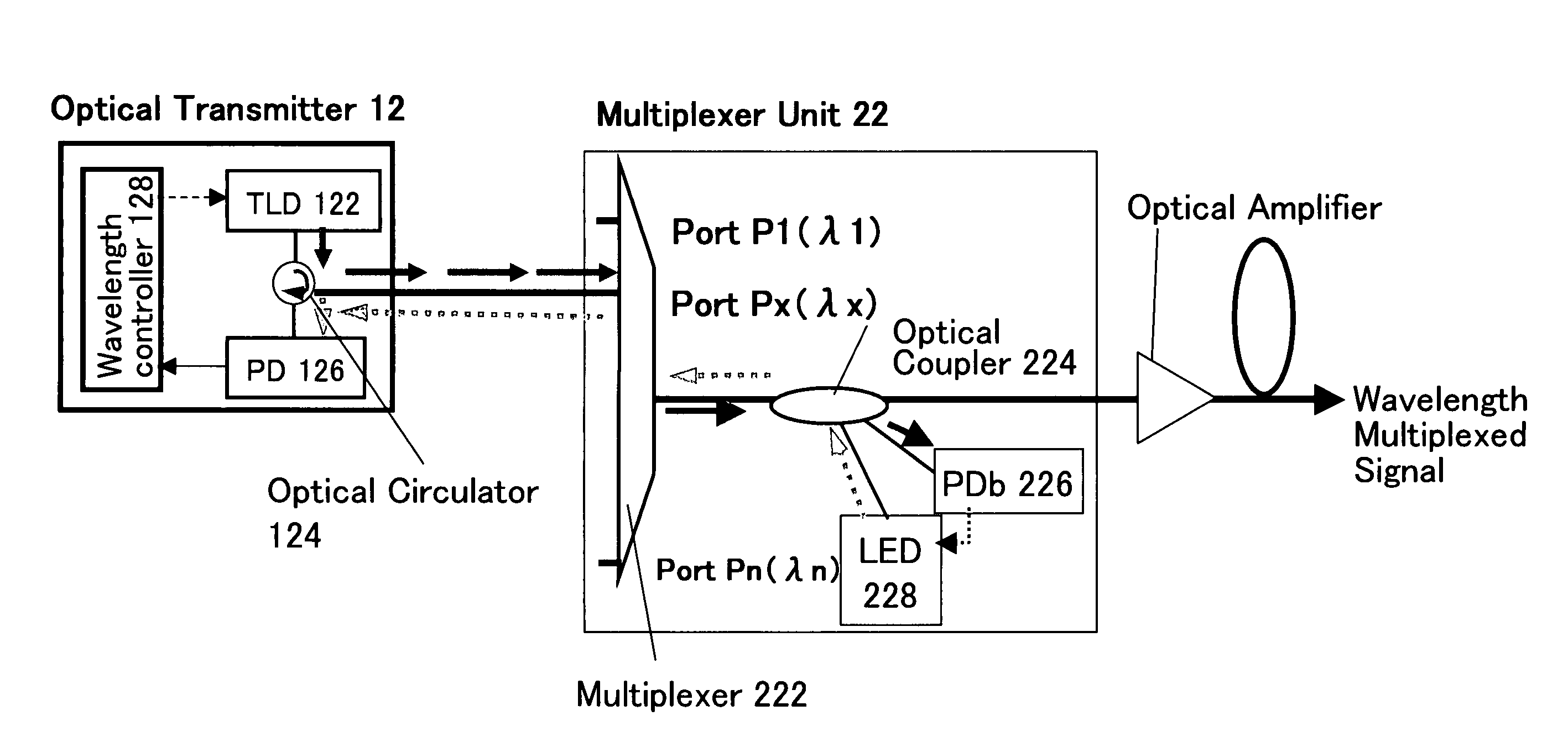
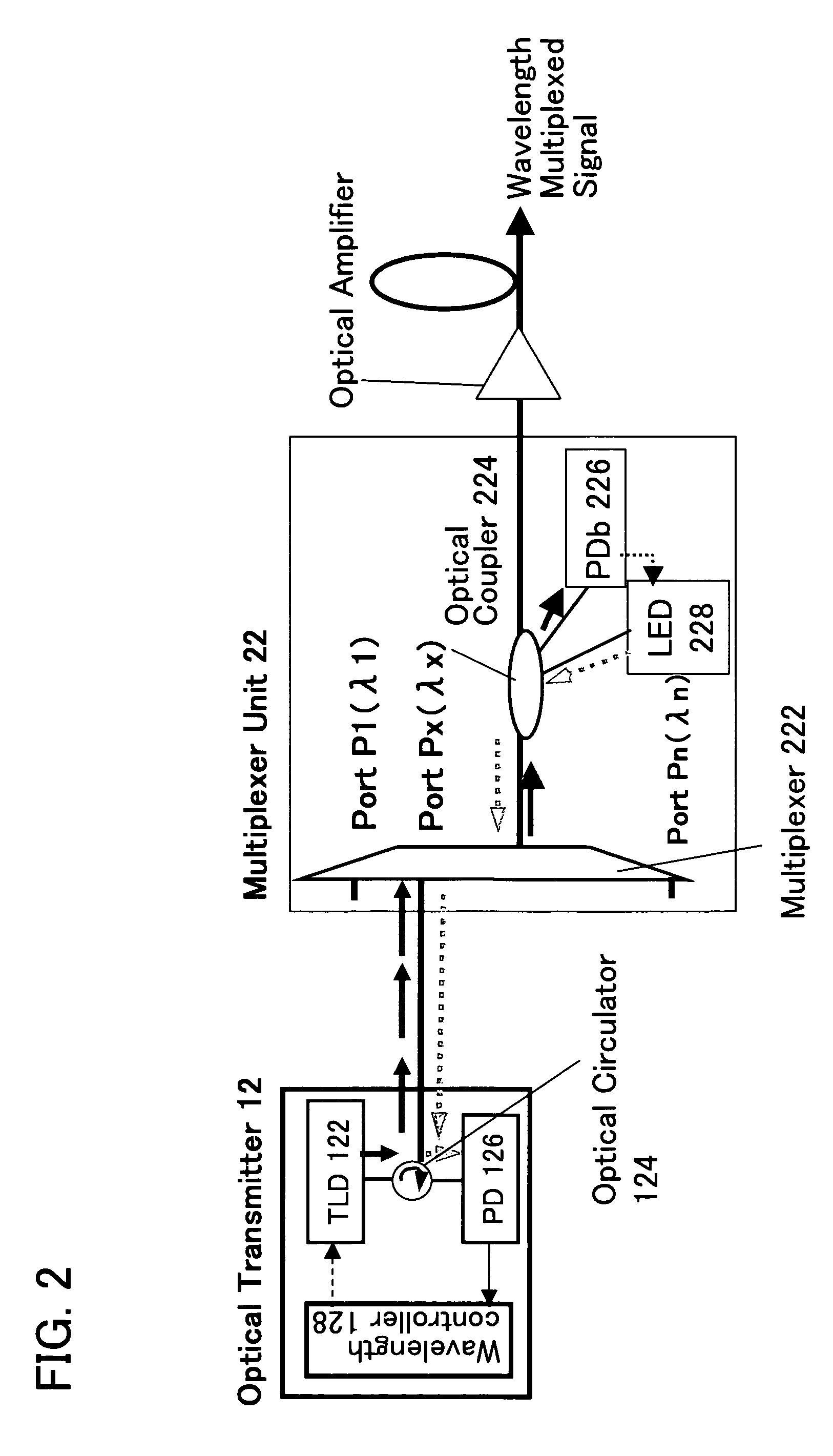
[0034]FIG. 2 shows a first exemplary configuration of a wavelength division multiplexing optical transmission system according to an embodiment of the present invention. In this FIG. 2, configurations of an optical transmitter 12 provided in a transmission unit and a multiplexer unit 22 provided in a WDM unit, respectively equipped on the transmission side of a wavelength division multiplexing optical transmission system according to the embodiment of the present invention. Optical transmitter 12 includes wavelength-variable (tunable) laser diode (TLD) 122, optical circulator 124, photodiode (PD) 126, and wavelength controller 128. Also, multiplexer unit 22 includes multiplexer 222, optical coupl...


PUM


Abstract

In the wavelength division multiplexing optical transmission system according to the present invention, when setting the transmission wavelengths of the wavelength-variable optical transmitter in case of addition or expansion of the optical transmitter, each transmission wavelength is set automatically so as to match with each port wavelength of the input port in the multiplexer. Therefore, the setting workload of the optical transmitter is remarkably reduced, and occurrence of incorrect setting can be avoided. Also, with a simple and low-cost structure, the cost is restrained from increasing.

Description

FIELD OF THE INVENTION[0001]The present invention relates to a wavelength division multiplexing optical transmission system and a method for controlling the transmission wavelengths of a plurality of wavelength-variable optical transmitters used in the wavelength division multiplexing optical transmission system.BACKGROUND OF THE INVENTION[0002]The wavelength division multiplexing (WDM) optical transmission system transmitting signals by multiplexing different wavelengths on a single optical fiber has been put into practical use as long haul and large capacity communication medium.[0003]FIG. 1 shows a diagram illustrating an overall configuration example of the wavelength division multiplexing optical transmission system. A transmission unit 10 is constituted of a plurality of optical transmitters 12-1, 12-2, . . . 12-n. From each optical transmitter, light of different wavelengths is transmitted and input into a multiplexer unit 22 in a WDM unit 20 on the transmission side. Multipl...

Claims


Application Information

Patent Timeline
Patent Type & Authority Patents(United States)
IPC IPC(8): H04J14/02H04J14/00H04B10/071
CPCH04B10/07H04B10/2503H04J14/02H04J14/025H04J14/0246H04J14/0279H04J14/0227H04B10/2589
Inventor NAKASHIMA, HISAOHOSHIDA, TAKESHI
Owner FUJITSU LTD
Why Eureka
Try Eureka