Capacitance multiplier circuit

a technology of capacitor and multiplier, which is applied in the direction of pulse manipulation, pulse technique, instruments, etc., can solve the problems of adverse effects on the stability of the overall circuit and the frequency response, and achieve the effect of increasing the effective capacitance of the capacitor

Active Publication Date: 2009-10-06
QUALCOMM INC
View PDF3 Cites 3 Cited by
  • Summary
  • Abstract
  • Description
  • Claims
  • Application Information

AI Technical Summary

Benefits of technology

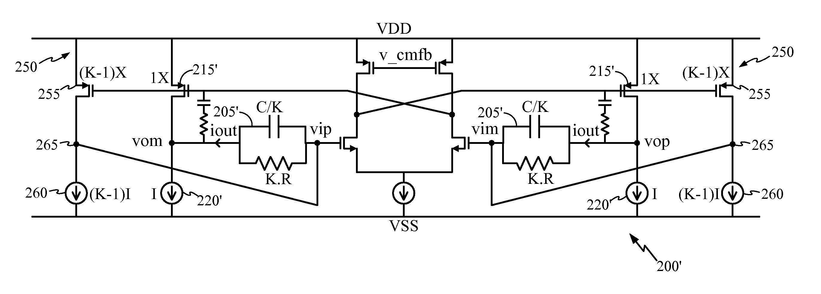
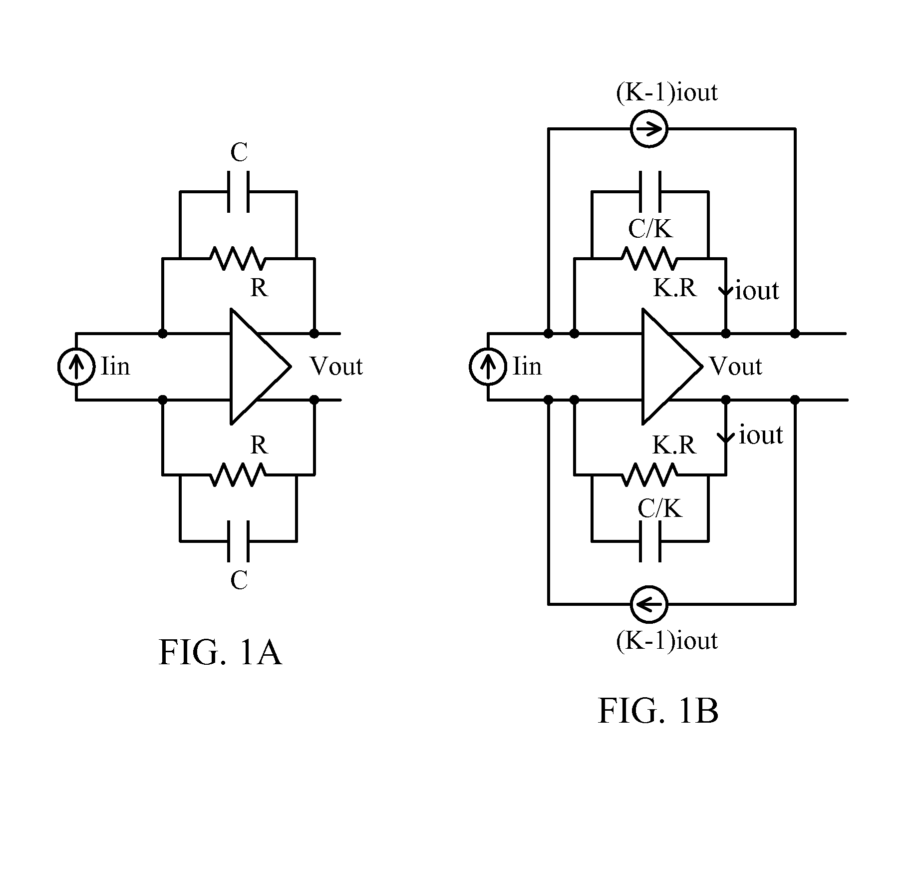
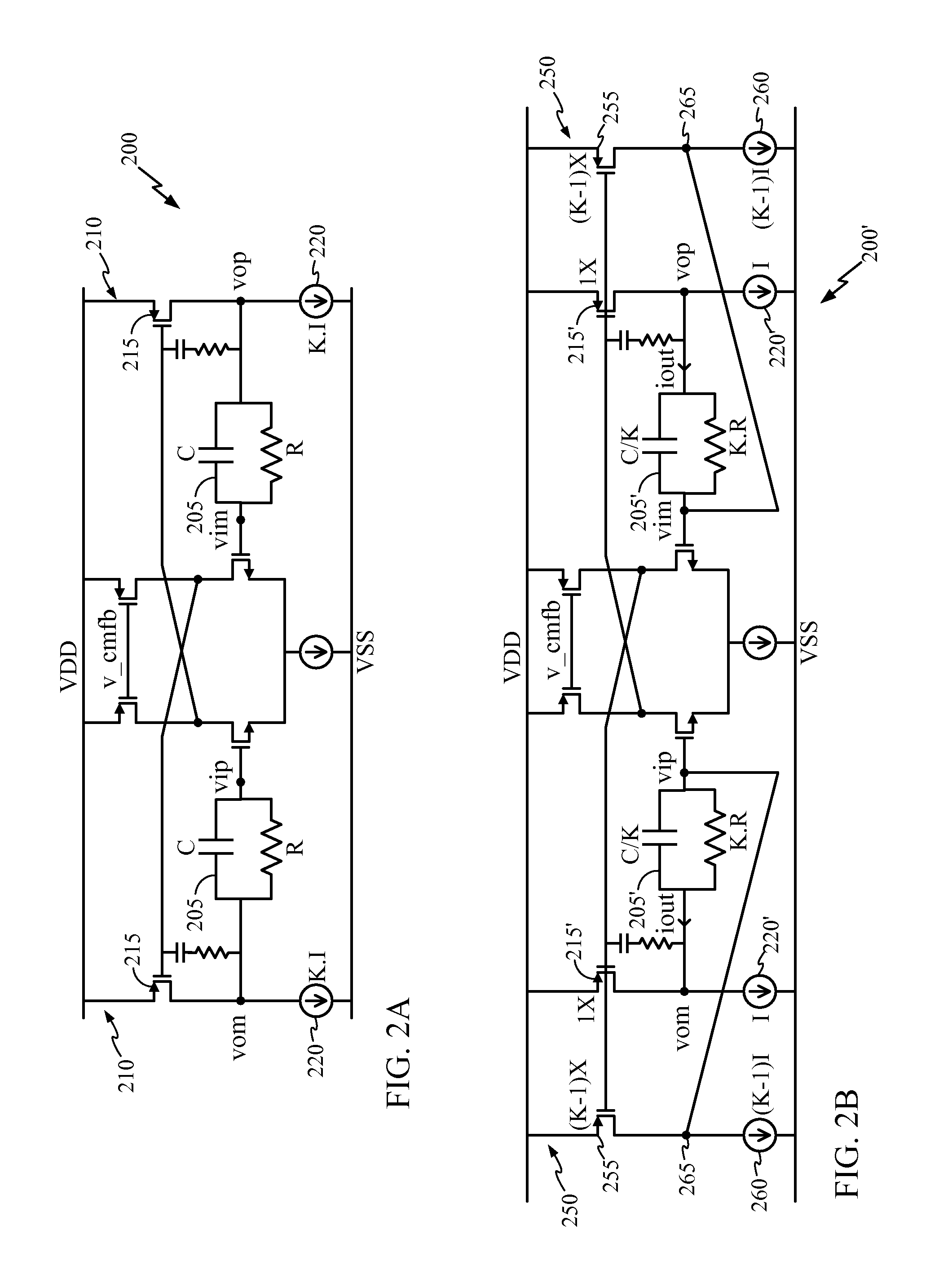
[0008]Another embodiment of the invention can include, an apparatus including a capacitance multiplier circuit, the circuit comprising: a filter having a resistor (R) in parallel with a capacitor (C); a first signal path coupled to a filter output; and a second signal path coupled to an input to the filter wherein a current output through the filter (iout) is split between the two paths, sensed in the first path and multiplied in the second path, the multiplied current being fed back from the second path to the filter input to increase the effective capacitance of th

Problems solved by technology

Accordingly, this additional circuitry is undesirable on a small chip surface, and

Method used


Image

  • Capacitance multiplier circuit
  • Capacitance multiplier circuit
  • Capacitance multiplier circuit

Examples


Embodiment Construction

[0019]Aspects of the invention are disclosed in the following description and related drawings directed to specific embodiments of the invention. Alternate embodiments may be devised without departing from the scope of the invention. Additionally, well-known elements of the invention will not be described in detail or will be omitted so as not to obscure the relevant details of the invention.

[0020]The word “exemplary” or “example” is used herein to mean “serving as an example, instance, or illustration.” Any embodiment described herein as “exemplary” is not necessarily to be construed as preferred or advantageous over other embodiments. Likewise, the term “embodiments of the invention” does not require that all embodiments of the invention include the discussed feature, advantage or mode of operation.

[0021]The terminology used herein is for the purpose of describing particular embodiments only and is not intended to be limiting of embodiments of the invention. As used herein, the si...


PUM


Abstract

A capacitance multiplier circuit is configured to sense a current through a capacitor in an RC filter of the circuit and to multiply the current so as to achieve a capacitance multiplier effect without adding additional circuitry or requiring additional power. The circuit includes an RC filter, a first signal path connected to a filter output, and a second signal path connected to an input to the filter. A current output through the filter (iout) is split between the two paths, sensed in the first path and multiplied in the second path. The multiplied current is fed back from the second path to the filter input to raise the effective capacitance of capacitor C. The capacitance multiplier circuit, in raising the effective capacitance of the capacitor in the filter, does not affect the frequency response, linearity performance and/or stability of the overall circuit.

Description

FIELD OF DISCLOSURE[0001]Example embodiments in general relate to a capacitance multiplier circuit and to a transimpedance amplifier (TIA) circuit having a capacitance multiplier.BACKGROUND[0002]Typically in system-on-chip (SoC) integration, on-chip capacitors occupy substantial silicon real estate, thus it is desirable to reduce the amount of surface area it takes up on the chip. One way to address this problem has been to employ capacitance multiplier circuits on the chip, so that a smaller 1× capacitor can be formed on the chip, but with capacitance multiplication is able to function in a circuit on the chip as a 5× or 10× capacitor, depending on the design requirements for capacitance in the circuit.[0003]Capacitance multipliers can be broadly classified into two basic categories; voltage-based capacitance multipliers such as Miller capacitance multipliers; and current-based capacitance multipliers. A Miller capacitance multiplier, in its basic form, senses a voltage through the...

Claims


Application Information

Patent Timeline
IPC IPC(8): H03H11/40
CPCH03F3/45183H03F3/45659H03H11/48H03H11/0416H03H11/405H03F2200/456H03F2203/45318H03F2203/45646H03F2203/45526H03H11/483
Inventor SENGUPTA, SUSANTABARNETT, KENNETH CHARLES
Owner QUALCOMM INC
Why Eureka
Try Eureka