Millimeter-wave-band radio communication method in which both a modulated signal and an unmodulated carrier are transmitted to a system with a receiver having plural receiving circuits

a radio communication method and millimeter wave band technology, applied in the field of millimeter wave band radio communication method and system, can solve the problems of increasing antenna cost and difficult to obtain the expected high gain performance, and achieve the effect of convenient use and high gain

Inactive Publication Date: 2009-10-06
NAT INST OF INFORMATION & COMM TECH
View PDF18 Cites 90 Cited by
  • Summary
  • Abstract
  • Description
  • Claims
  • Application Information

AI Technical Summary

Benefits of technology

[0009]The object of the present invention is to solve the above-described problem and to enable construction of a low-cost radio communication system, transmission of high-quality signals, and production of a wide beam antenna which has a high gain and which is convenient for use.

Problems solved by technology

However, several problems may arise when an actual radio system is designed and constructed.
Therefore, cost of the antenna increases, or obtaining an expected high gain performance becomes very difficult.

Method used


Image

  • Millimeter-wave-band radio communication method in which both a modulated signal and an unmodulated carrier are transmitted to a system with a receiver having plural receiving circuits
  • Millimeter-wave-band radio communication method in which both a modulated signal and an unmodulated carrier are transmitted to a system with a receiver having plural receiving circuits
  • Millimeter-wave-band radio communication method in which both a modulated signal and an unmodulated carrier are transmitted to a system with a receiver having plural receiving circuits

Examples


embodiment 1

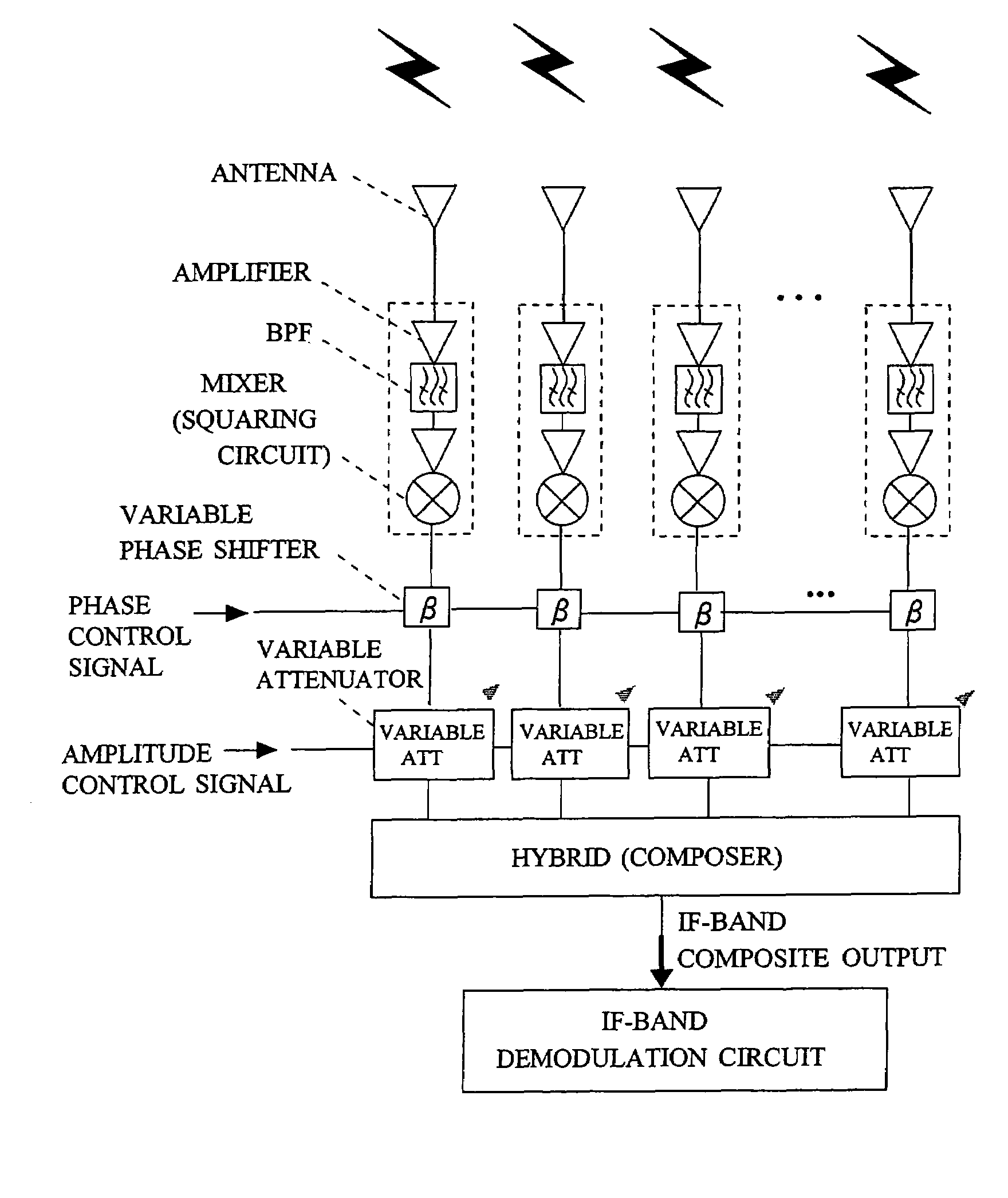
[0030]FIG. 4 is a diagram showing a receiving circuit (Embodiment 1) which embodies the basic configuration shown in FIG. 1. In Embodiment 1, at the time of mixing IF outputs, phase adjustment and amplitude weighting are performed for the IF outputs to be mixed, whereby the receiving beam pattern can be controlled. In the illustrated example, each IF output is passed through a variable phase shifter and a variable attenuator, and is then fed to a composer for power mixing. In the variable phase shifter β, the phase of the IF output is adjusted on the basis of a phase control signal. In the variable attenuator (variable ATT), amplitude weighting is performed for the IF output on the basis of an amplitude control signal. Notably, in place of the above configuration for analog control, there can be employed digital beam forming in which the IF outputs are converted to digital outputs, and digital processing is performed for the digital outputs.

[0031]The illustrated configuration enable...

embodiment 2

[0033]FIG. 5 is a diagram showing a receiving circuit (Embodiment 2) which embodies the basic configuration shown in FIG. 1. In the illustrated example, three or more (a plurality of) unit receiving circuits (receiving antennas) are not disposed at constant intervals, but are disposed irregularly; e.g., at prime intervals or logarithmic distribution intervals. Even in the case where two or more receiving circuits are disposed, if the intervals are constant, signal phasing inevitably occurs under a certain condition (at a certain distance between the millimeter-wave transmitter and receiver or at a certain height). In contrast, when three or more receiving circuits are disposed at irregular intervals, signal phasing can be prevented in most cases.

embodiment 3

[0034]FIGS. 6(A) and 6(B) are diagrams showing a receiving circuit (Embodiment 3) which embodies the basic configuration shown in FIG. 1. In the receiver configuration shown in FIG. 6(A), a plurality of unit receiving circuits are not arranged on a circuit arrangement plane along a certain direction, but are arranged two-dimensionally; i.e., along directions (transverse direction and longitudinal direction) which intersect at angles of 90°, and outputs of the unit receiving circuits are mixed. Alternatively, as shown in FIG. 6(B), a plurality of unit receiving circuits may be arranged three-dimensionally by arranging them on a spherical surface or the surface of a cube.

[0035]In general, a multi path phenomenon occurs in both the vertical and horizontal directions, rather than in just one of these directions. Accordingly, through employment of the illustrated arrangement, multi-path phasing generated in any direction can be avoided.


PUM


Abstract

A receiver receives an RF-band modulated signal transmitted from a transmitter, as well as an un-modulated carrier also transmitted from the transmitter and having a phase noise characteristic coherent with that of the modulated signal, and a product of the two components is generated to thereby restore an IF-band transmission source signal. In the receiver, a small planar antenna having a broad beam characteristic such as a single-element patch antenna is combined with an amplifier and a mixer circuit, which are formed on a micro planar circuit by an MMIC technique, so as to form a unit receiving circuit. A plurality of such unit receiving circuits are disposed on the receiver at intervals smaller than a wavelength corresponding to an IF band, and detection outputs from the unit receiving circuits are power-mixed. Thus, the receiver serves as a high-gain antenna having a detection function, and can realize a broad beam radiation characteristic comparable to that of a single-element antenna. The composed IF-band composite output is demodulated in an IF-band demodulation circuit. The present invention enables construction of a low-cost radio communication system, transmission of high-quality signals, and production of a wide beam antenna which has a high gain and which is convenient for use.

Description

[0001]This application claims the benefit of PCT International Application Number PCT / JP03 / 09585 filed Jul. 29, 2003, the disclosure of which are incorporated herein by reference.TECHNICAL FIELD[0002]The present invention relates to a millimeter-wave-band radio communication method and system in which an RF-band modulated signal transmitted from a transmitter and a local oscillation signal also transmitted from the transmitter and having a phase noise characteristic coherent with that of the modulated signal are received by a receiver, and a product of the two components is generated to thereby restore an IF-band transmission source signal.BACKGROUND ART[0003]In general, a radio apparatus for transmitting a high-speed digital signal, a broadband analog signal, or the like is composed of a transmitter having a function of producing a product of an intermediate-frequency (IF) band signal and a local oscillation (LO) signal and performing up-conversion so as to generate and transmit a ...

Claims


Application Information

Patent Timeline
Patent Type & Authority Patents(United States)
IPC IPC(8): H04B7/08H01Q3/26H01Q21/08
CPCH01Q3/26H01Q3/30H04B7/0845H04B1/22H01Q21/08
Inventor SHOJI, YOZOHAMAGUCHI, KIYOSHIOGAWA, HIROYO
Owner NAT INST OF INFORMATION & COMM TECH
Why Eureka
Try Eureka