System and apparatus for complete condensation of multi-component working fluids

a multi-component working fluid and system technology, applied in the direction of lighting and heating apparatus, defrosting, cooling apparatus, etc., can solve the problems of increasing condensation pressure, uncondensable vapor accumulation in the condenser, and inability to achieve condensation stability and efficiency, and improving condensation stability and efficiency , the effect of improving condensation stability and efficiency

Inactive Publication Date: 2009-10-13
KALINA POWER LTD
View PDF25 Cites 28 Cited by
  • Summary
  • Abstract
  • Description
  • Claims
  • Application Information

AI Technical Summary

Benefits of technology

[0009]The present invention provides a method for preventing accumulation of non-condensable vapor in a condensation apparatus adapted to produce a fully condensed multi-component working fluid for return to a power system or other facility that uses fully condensed multi-component working fluids. The method includes the step of feeding an incoming vapor multi-component stream into a first heat exchange unit, which condenses the stream in counter-flow with an external coolant to form a condensate and an non-condensable vapor. A major portion of the condensate is divided from a condensate stream withdrawn from the first heat exchange unit to form an outgoing fully condensed multi-component fluid and a minor portion of the condensate stream forms an absorbent stream. The absorbent stream is forwarded to a second heat exchange unit, where it is sub-cooled in counter-flow with an external coolant to form a sub-cooled absorbent stream. The sub-cooled absorbent stream is then injected (pumped) into the first heat exchange unit through a sprayer above a liquid level in the first heat exchange unit. The sub-cooled absorbent stream is sufficient to absorb an amount of non-condensable vapor reducing its accumulation in the apparatus and improving condensation stability and efficiency. The method can optionally include feeding the entire condensate stream and a non-condensable vapor stream to a receiver. The condensate in the receiver is then withdrawn and separated into the outgoing multi-component working fluid stream and the absorbent stream. The absorbent stream is then sub-cooled and pumped into a vapor section of the receiver through a sprayer, where the sub-cooled absorbent stream is sufficient to absorb an amount of non-condensable vapor reducing its accumulation in the apparatus and improving condensation stability and efficiency.
[0010]The present invention also provides an apparatus designed to prevent the accumulation of non-condensable or uncondensable vapor and to provide efficient and stable operation of a condenser in a condensation system adapted to produce fully condensed multi-component working fluid streams. The apparatus includes a first heat exchange unit, a dividing valve and a second heat exchange unit. The first heat exchange unit is adapted to condense a vapor incoming multi-component working fluid stream. The condensate is forwarded to the dividing valve, which divides the condensate into a outgoing fully condensed working fluid stream comprising a major portion of the condensate and an absorbent stream comprising a minor portion of the condensate. The absorbent stream is fed to the second heat exchange unit, where it is sub-cooled to form a sub-cooled absorbent stream. The sub-cooled absorbent stream is then pumped into the first heat exchange unit through a sprayer above a liquid level, where the sub-cooled absorbent stream is sufficient to absorb an amount of non-condensable vapor reducing its accumulation in the apparatus and improving condensation stability and efficiency. The apparatus can also includes a receiver adapted to receive the entire condensate from the first heat exchange unit and the non-condensable vapor. The receiver include a vapor section and a condensate or liquid section. The condensate is then withdrawn from the receiver and divided in a dividing value into the out-going fully condensed multi-component working fluid stream and the absorbent stream. The absorbent stream is then sub-cooled in the second heat exchange unit and pump into the vapor section of the receiver through a sprayer, where the sub-cooled absorbent stream is sufficient to absorb an amount of non-condensable vapor reducing its accumulation in the apparatus and improving condensation stability and efficiency.

Problems solved by technology

As a result, a composition of the liquid or condensate and a composition of the vapor are not in equilibrium.
Over time, this uncondensable vapor accumulates in the condenser and inhibits heat transfer.
As a result, the pressure of condensation increases and this increase has a negative impact on performance of the condenser, and on a power system that includes the condensation process as a whole.

Method used


Image

  • System and apparatus for complete condensation of multi-component working fluids
  • System and apparatus for complete condensation of multi-component working fluids
  • System and apparatus for complete condensation of multi-component working fluids

Examples


first embodiment

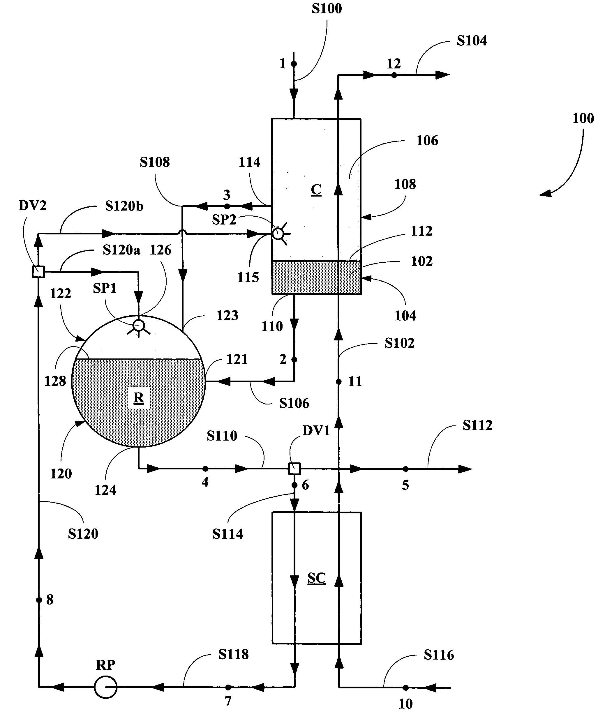
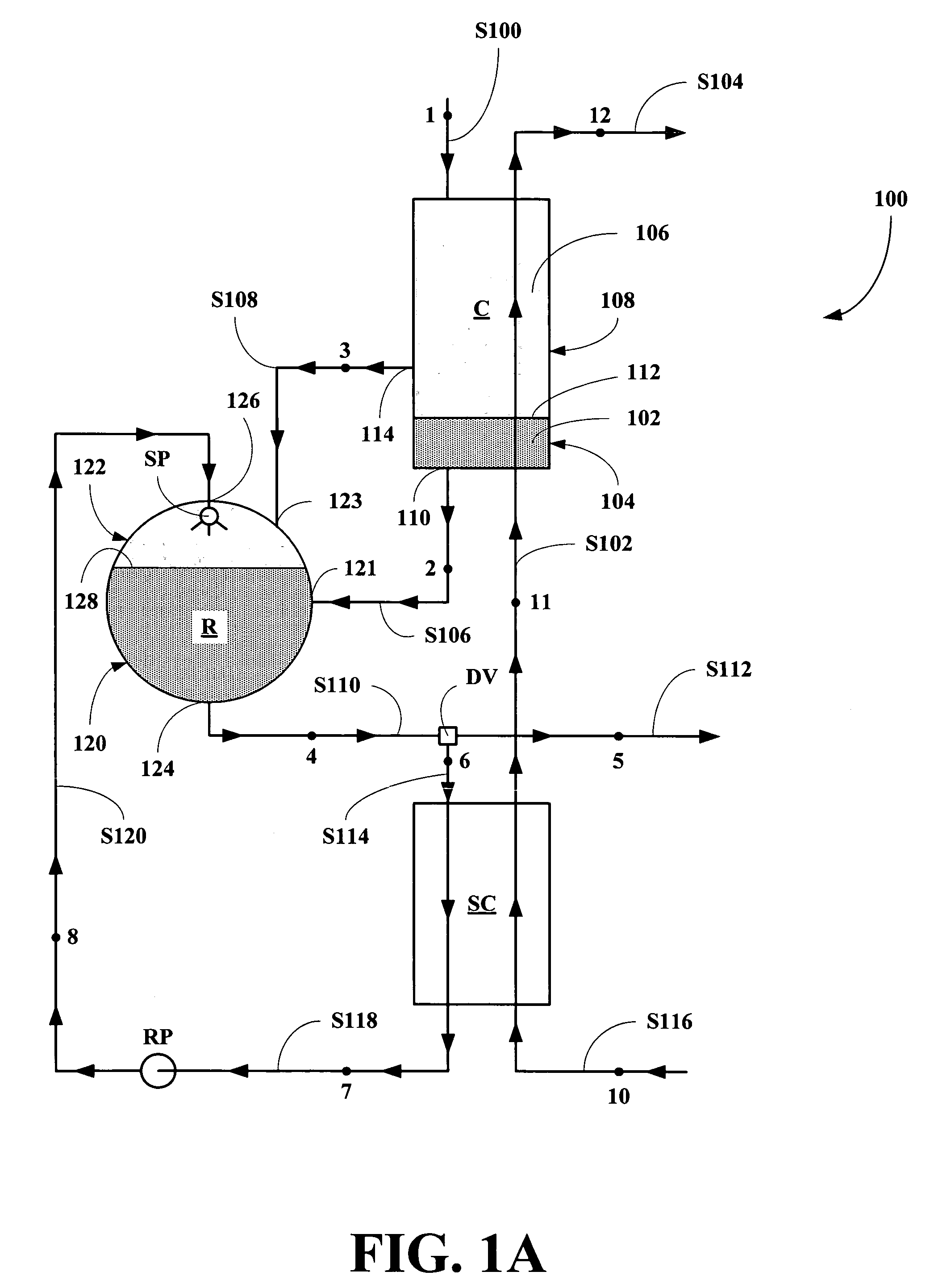
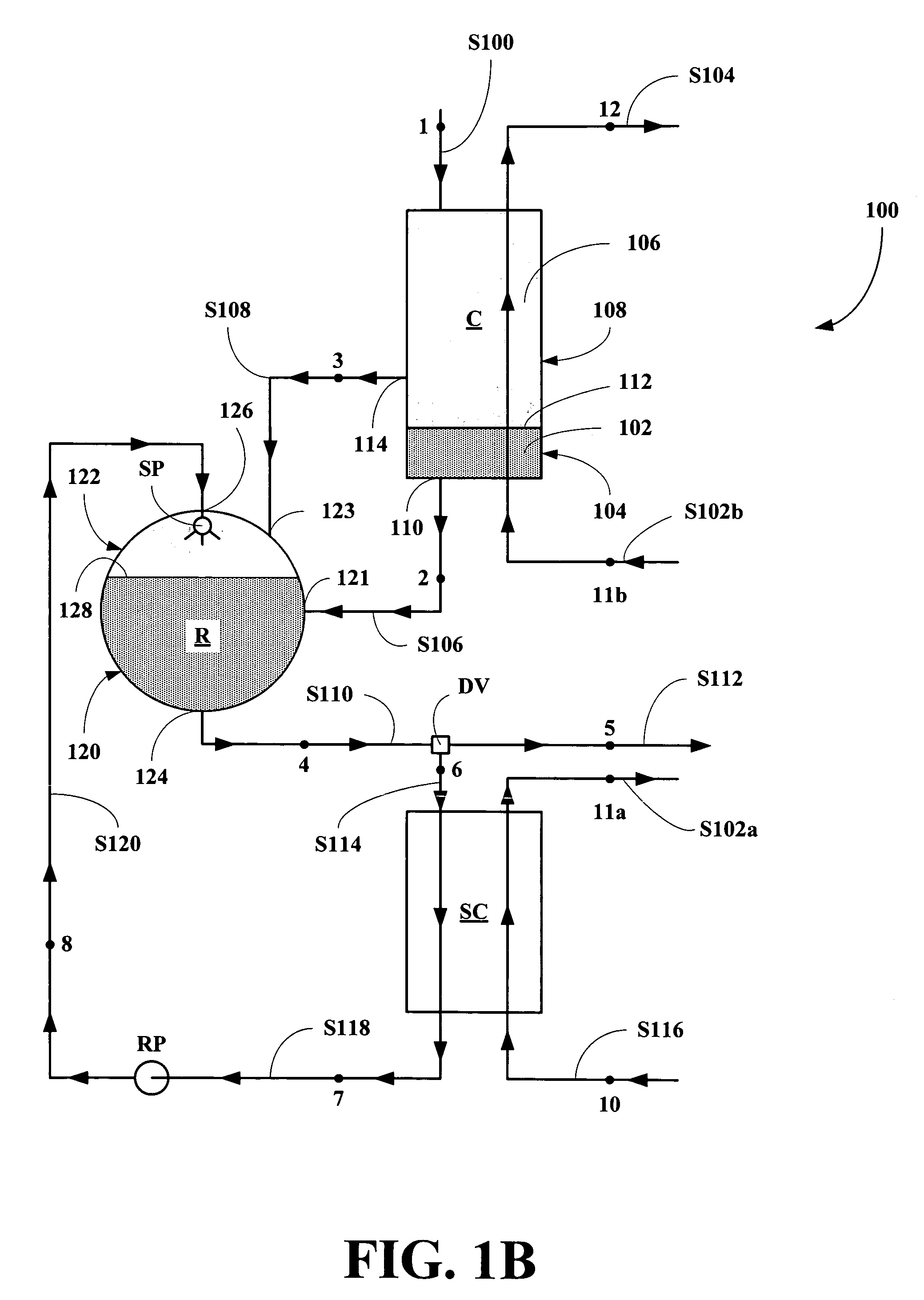
[0027]Referring now to FIG. 1, a conceptual flow diagram of an embodiment of a condensation system and apparatus of this invention, generally 100, is shown. A spent power system stream S100 having parameters as at a point 1, enters into a condenser C of the system 100 from a power system (not shown), where it is cooled in counter-flow by a heated coolant stream S102 having parameters as at a point 11 in a first heat exchange step 11-12 to form a spent coolant stream S104 having parameters as at a point 12. In the condenser C, the coolant stream S102 causes the spent power system stream S100 to condense to form a condensate 102 that accumulates in a bottom 104 of the condenser C and a non-condensable vapor 106 that accumulates in the remainder 108 of the condenser C. The condensate 102 is removed from a bottom outlet 110 of the condenser C as a condensate stream S106 having parameters as at a point 2. The condensate stream S106 having the parameters as at the point 2 is then forwarde...

second embodiment

[0037]Referring now to FIG. 2A, a second embodiment of a condensation apparatus and system of this invention, generally 200, is shown. A spent power system stream S200 having parameters as at a point 1, enters into a condenser C of the system 200 from a power system (not shown), where it is cooled in counter-flow by a heated coolant stream S202 having parameters as at a point 11 in a first heat exchange step 11-12 to form a spent coolant stream S204 having parameters as at a point 12. In the condenser C, the coolant stream S202 causes the spent power system stream S200 to partially condense to form a condensate 202 that accumulates in a bottom 204 of the condenser C and a vapor 206 that accumulates in the remainder 208 of the condenser C. The condensate 202 is removed from a bottom outlet 210 of the condenser C as a condensate stream S206 having parameters as at a point 2. The condensate stream S206 having the parameters as at the point 2 is then forwarded to a dividing valve DV, wh...

third embodiment

[0042]Referring now to FIG. 3, a third embodiment of a condensation apparatus and system, generally 300 is shown. A spent power system stream S300 having parameters as at a point 1, enters into an gas cooled condenser C of the system 300, where it is cooled in counter-flow with a heated gas coolant stream S302 in a first heat exchange process to form a spent gas stream S304 and a partially condensed stream S307 having parameters as at points 2 and 3. The stream S307 having the parameters as at the point 2 or 3 is then forwarded to a liquid portion 320 a receiver R via a liquid inlet 321.

[0043]A liquid stream S310 having parameters as at a point 4 is then removed from a bottom outlet 324 of the receiver R and divided in a dividing valve DV into a first liquid substream S312 having parameters as at a point 5 and a second liquid substream or absorbent stream S314 having parameters as at a point 6. The absorbent stream S312 having the parameters as at the point 5 is then returned to the...


PUM


Abstract

A condensation system is disclosed where a multi-component fluid is condensed to form a condensate, a portion of which is sub-cooled and mixed with non-condensable vapor in the system to reduce the accumulation of non-condensable vapor and to improve the stability and efficiency of the condensation system.

Description

BACKGROUND OF THE INVENTION[0001]1. Field of the Invention[0002]The present invention relates to a system and an apparatus for complete condensation of multe-component working fluids.[0003]More particularly, the present invention relates to a system and an apparatus for complete condensation of multi-component working fluids, where the apparatus includes a condenser, a sub-cooler and a dividing valve. The condenser is adapted to condense a multi-component fluid in counter flow with a coolant stream to produce a condensate and a non-condensable vapor. The dividing valve is adapted to split a condensate stream exiting the condenser into a fully condensed multi-component working fluid stream which is returned to a power plant and an absorbent stream. The sub-cooler sub-cools the absorbent stream which is pumped through a sprayer into a vapor section of the condenser, where sub-cooled absorbent stream is sufficient to absorb an amount of non-condensable vapor reducing its accumulation i...

Claims


Application Information

Patent Timeline
Patent Type & Authority Patents(United States)
IPC IPC(8): F25J1/00F25B39/04
CPCF01K25/06F25J1/0279F28B1/02F25J1/0296F28B9/08F28B9/10F25J1/0092F25J1/0097F28B1/06F25B43/04Y10S165/185Y10S165/206Y02P80/15
Inventor KALINA, ALEXANDER I.
Owner KALINA POWER LTD
Why Eureka
Try Eureka