Integrated fluid catalytic cracking process

a technology of integrated fluid and catalytic cracking, which is applied in the direction of hydrocarbon oil treatment products, physical/chemical process catalysts, furnaces, etc., can solve the problem that the demand for light olefins is outpacing the capacity of traditional sources of light olefins

Inactive Publication Date: 2009-10-13
UOP LLC
View PDF12 Cites 11 Cited by
  • Summary
  • Abstract
  • Description
  • Claims
  • Application Information

AI Technical Summary

Problems solved by technology

However, the demand for light olefins is outstripping the capacity of traditional sources of light olefins.

Method used


Image

  • Integrated fluid catalytic cracking process
  • Integrated fluid catalytic cracking process

Examples


Embodiment Construction

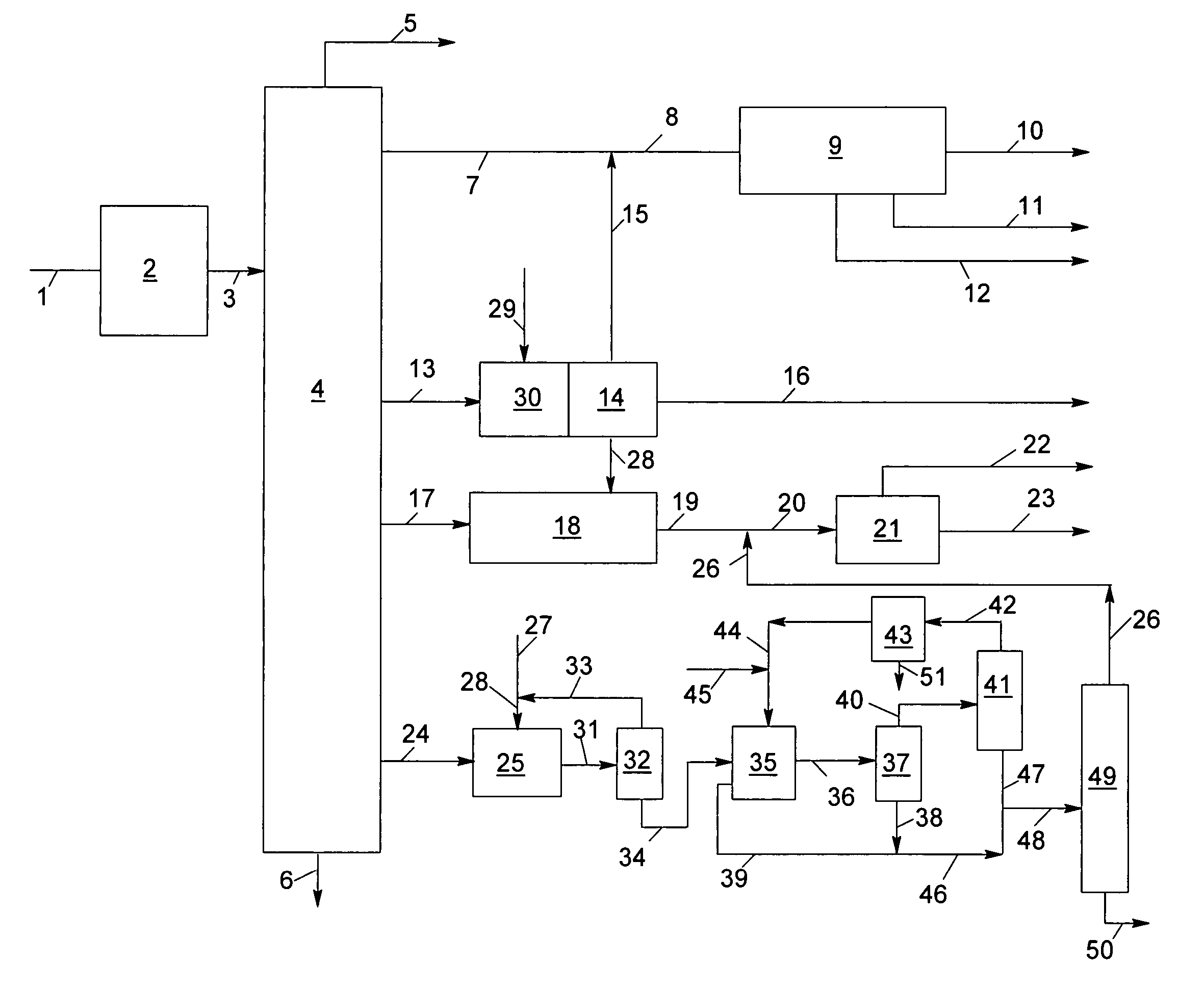
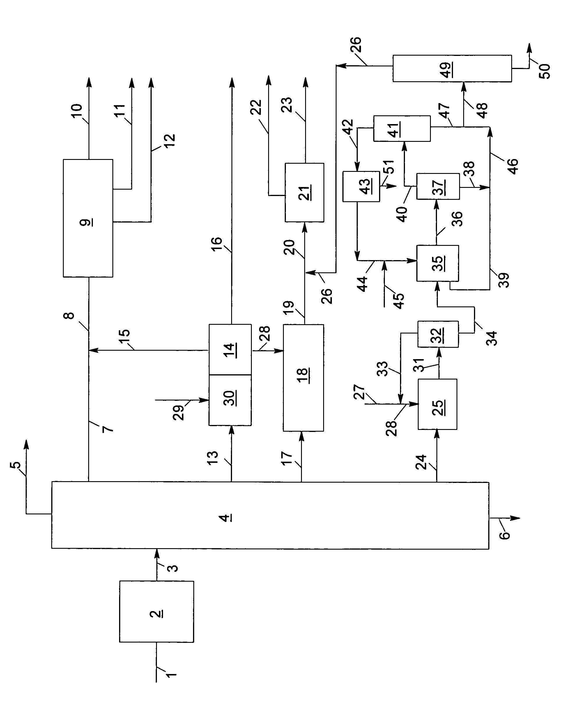
[0010]In accordance with the present invention, a suitable hydrocarbon feedstock may be selected from the group consisting of gas oil, vacuum gas oil and atmospheric residue. The selected feedstock is introduced into a fluid catalytic cracking zone and contacted with a catalyst composed of finely divided particulate catalyst. The reaction of the feedstock in the presence of catalyst is accomplished in the absence of added hydrogen or the net consumption of hydrogen. As the cracking reaction proceeds, substantial amounts of coke are deposited on the catalyst. The catalyst is regenerated at high temperatures by burning coke from the catalyst in a regeneration zone. Coke-containing catalyst, referred to herein as “coked catalyst,” is continually transported from the reaction zone to the regeneration zone to be regenerated and replaced by coke-free regenerated catalyst from the regeneration zones. Fluidization of the catalyst particles by various gaseous streams allows the transport of ...


PUM


Abstract

A process for the conversion of a hydrocarbon feedstock to produce olefins, aromatic compounds and ultra low sulfur diesel wherein the hydrocarbon feedstock is reacted in a fluid catalytic cracking (FCC) zone to produce olefins and light cycle oil. The effluent from the FCC is preferably separated to produce a stream comprising ethylene and propylene, a stream comprising higher boiling olefins and light cycle oil (LCO). The stream containing the higher boiling olefins is cracked to provide additional ethylene and propylene. The LCO is selectively hydrocracked to produce aromatic compounds and ultra low sulfur diesel.

Description

FIELD OF THE INVENTION[0001]The present invention relates to an integrated fluid catalytic cracking (FCC) process for the conversion of a hydrocarbon feedstock to produce low molecular weight olefins, aromatic compounds and ultra low sulfur diesel.BACKGROUND OF THE INVENTION[0002]Light or low molecular weight olefins such as ethylene and propylene, for example, serve as feeds for plastics production and for the production of petrochemicals which serve as feeds for plastics production. The demand for light olefins has been steadily increasing and will continue to increase dramatically. Light olefins have traditionally been produced through the process of steam or catalytic cracking. Paraffin dehydrogenation is an alternative source of light olefins. However, the demand for light olefins is outstripping the capacity of traditional sources of light olefins.[0003]It has been recognized that due to environmental concerns and newly enacted rules and regulations, saleable products must mee...

Claims


Application Information

Patent Timeline
Patent Type & Authority Patents(United States)
IPC IPC(8): B01J8/18
CPCC10G11/05C10G51/04C10G53/02C10G69/04C10G69/14C10G11/18B01J29/00B01J29/064B01J29/12C10G2400/04
Inventor GOSLING, CHRISTOPHER D.
Owner UOP LLC
Why Eureka
Try Eureka