Laser pyrolysis method for producing carbon nano-spheres

a carbon nanoparticle and laser pyrolysis technology, applied in the field of nanotechnology, can solve the problems of insufficient or insufficient current technology in one or more fields, heterogeneous products of such conventional syntheses, and difficulty or inability to purify, and achieves high purity, low cost, and homogeneity and other properties.

Inactive Publication Date: 2009-10-13
MCKINNON J THOMAS +2
View PDF2 Cites 8 Cited by
  • Summary
  • Abstract
  • Description
  • Claims
  • Application Information

AI Technical Summary

Benefits of technology

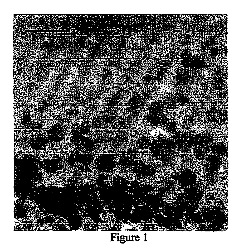
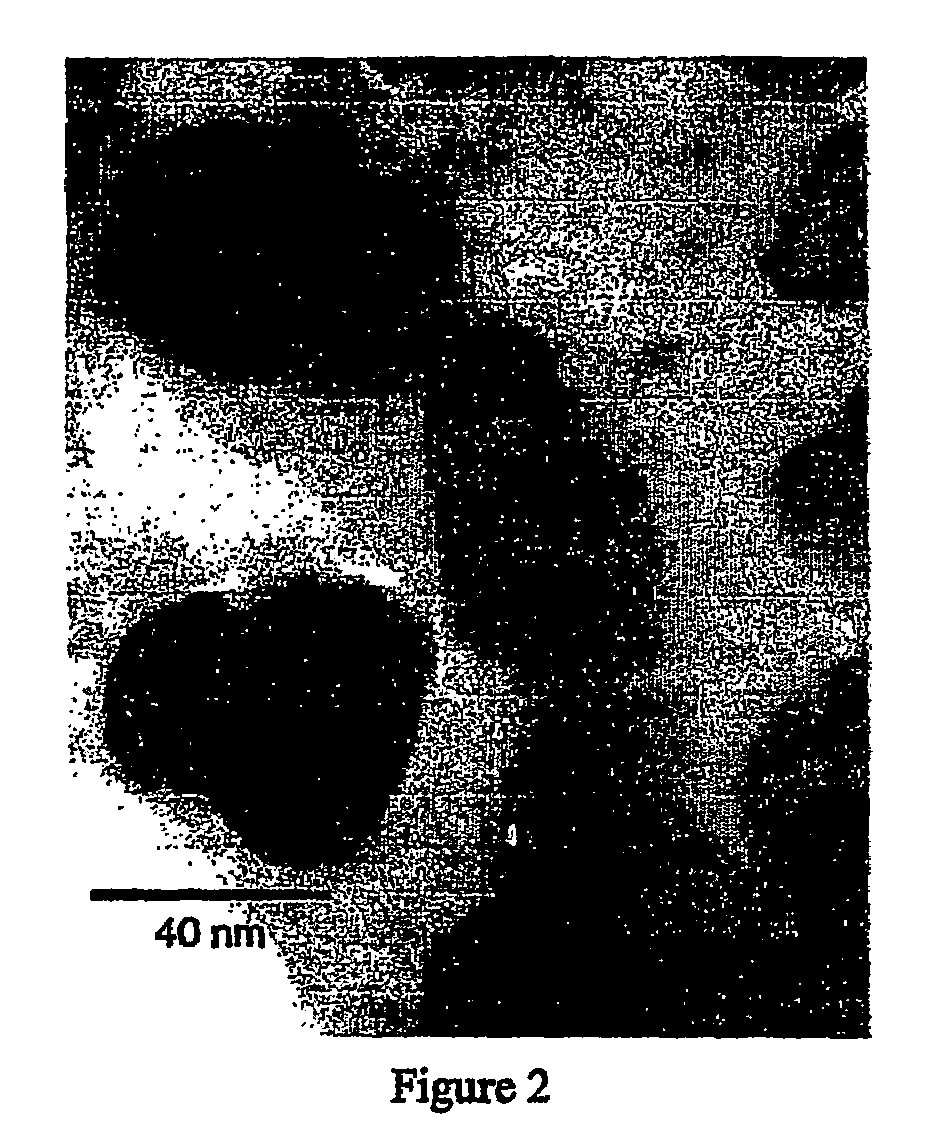
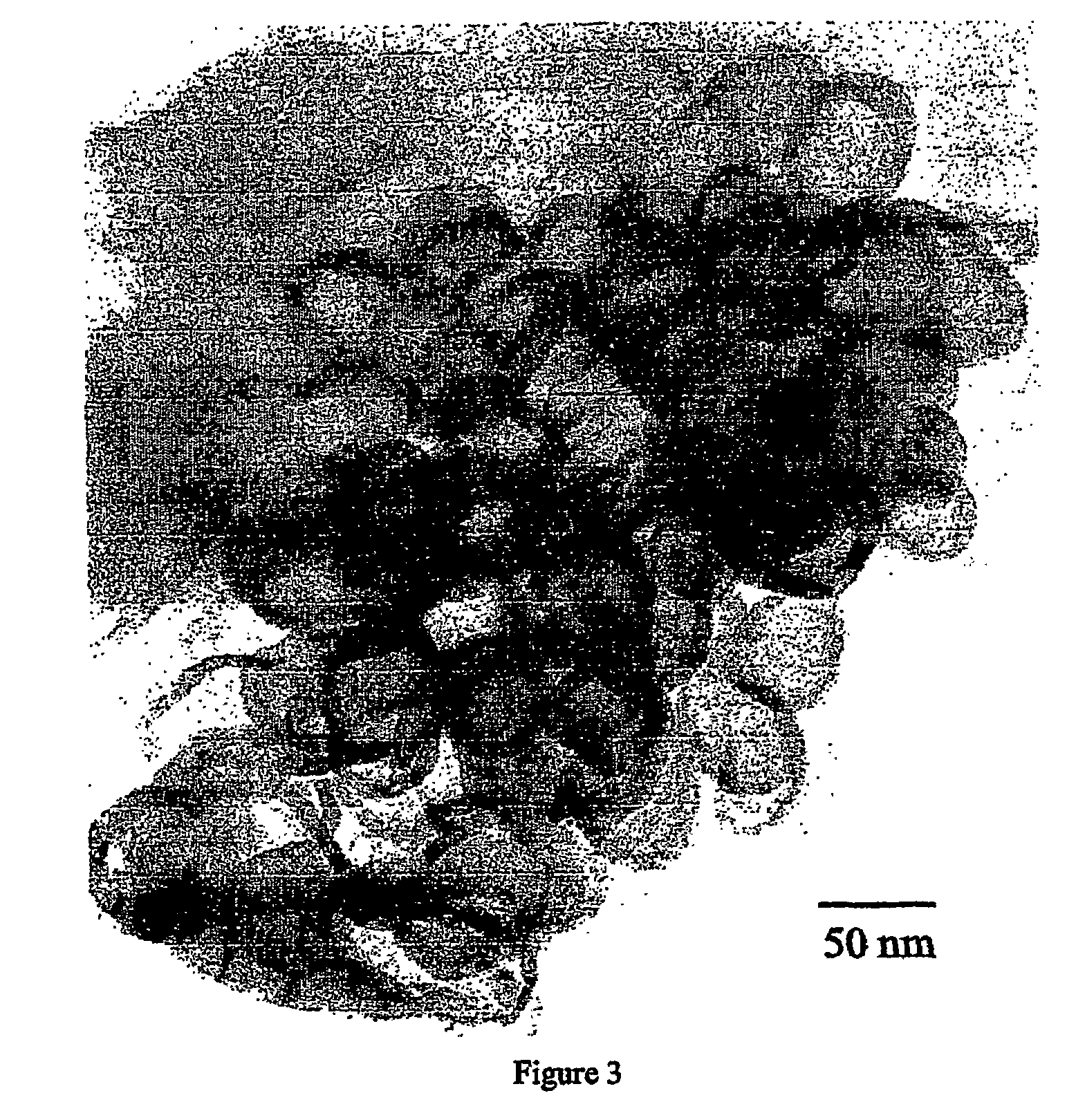
[0024]After being formed during the high temperature pyrolysis step described above, the carbon nanospheres can be removed from the amorphous carbon that surrounds them, for example by digesting the amorphous material in concentrated nitric acid. The nanosphere structures formed in accordance with this invention are substantially if not totally resistant to attack by the acid. Transmission electron microscope (TEM) analysis of nanospheres formed in accordance with this invention shows that the samples are almost totally homogenous. That is, they are uniform in size (for example, about 30-40 nm in diameter) with very little or no foreign material. The present invention provides a means of manufacturing large quantities of such nanospheres having superior purity, homogeneity and other properties for relatively low cost compared with prior art techniques.

Problems solved by technology

Furthermore, the products of such conventional syntheses are often heterogeneous, typically being mixed with large amounts of undesirable materials and therefore being difficult or impossible to purify.
The current technology in this field, however, is deficient or inadequate in one or more of the following ways:1. Expensive processing operations to create the nanoparticle products.2. Expensive materials or catalysts required to create the nanoparticle products.3. Nanoparticle products are produced in low yields.4. Nanoparticle products are produced in low purity.5. Nanoparticle products are difficult or impossible to obtain in pure form.6. Nanoparticle products are not in the best morphological configurations for use in the desired applications.

Method used


Image

  • Laser pyrolysis method for producing carbon nano-spheres
  • Laser pyrolysis method for producing carbon nano-spheres
  • Laser pyrolysis method for producing carbon nano-spheres

Examples


Embodiment Construction

[0034]The present invention is based on the novel discovery that the chemistry of charring carbonaceous substrate materials, particularly cellulose, can be modified in various surprising and advantageous ways by the addition of certain particular types of metals, e.g., in the form of metal salts, which can act as a template for the charring material. Furthermore, these metal particles embedded in the char have also been found to favorably influence the subsequent pyrolysis chemistry and allow the production of the desired carbon nanoparticle morphology. Finally, the intermediate production and isolation of the nano-sized metal templates (metal nanoparticles) in accordance with this invention is a further desired outcome.

[0035]Transition metals have been known previously for their efficient production of single- and multi-wall nanotubes. See, for example, Colomer, J. F.; Bister, G.; Willems, I.; Kónya; Fonseca, A.; Van Tendeloo, G.; Nagy, J. B. Chem Commun. 1999, 1343, which literatu...


PUM

PropertyMeasurementUnit
temperatureaaaaaaaaaa
wt. %aaaaaaaaaa

Abstract

The present invention encompasses methods and apparatus for creating metal nanoparticles embedded in a carbonaceous char, the conversion of an carbonaceous char with embedded metallic nanoparticles to graphite-encased nano-sized metal particles surrounded by char, the separation of the graphite encased metal particles from the char matrix, and the related preparation and isolation of carbon nanosphere materials with or without the enclosed metal nanoparticles, and the uses of such carbon nanospheres and graphite enclosed metal nanoparticles as supports and enhancers for fuel cell electrocatalysts and other applications.

Description

CROSS-REFERENCE TO RELATED APPLICATIONS[0001]This application claims the benefit of the filing date of international application PCT / US04 / 04454 filed Feb. 17, 2004, which claims the benfit of the filing date of U.S. Provisional Application Ser. No. 60 / 448,924 filed Feb. 22, 2003.FIELD OF THE INVENTION[0002]The present invention relates generally to the field of nanotechnology and specifically to improved methods for the synthesis of carbon nanoparticles. This invention provides a novel method for the laser pyrolysis production of relatively homogeneous samples of hollow carbon nanospheres, and related intermediate products, derived via template synthesis, mediated by metal salts, from a carbonaceous substrate, preferably cellulose char, an inexpensive and renewable precursor. Such nanospheres and related products have many potential uses, for example as blends in nanocomposites (e.g., in polymers and high temperature glasses), as catalyst supports, and as nanoreaction chambers. Such...

Claims


Application Information

Patent Timeline
Patent Type & Authority Patents(United States)
IPC IPC(8): C01B31/02B22F1/054B22F1/102C01B
CPCB22F1/0018B22F9/20B82Y30/00B82Y40/00C01B31/00C01B31/02C01B31/0206H01M4/92H01M4/926B22F1/0062B22F9/04Y02E60/50B22F2998/00H01M2008/1095B22F2202/11B22F2201/03C01B32/00C01B32/05C01B32/15B22F1/102B22F1/054
Inventor MCKINNON, J. THOMASHERRING, ANDREW M.MCCLOSKEY, BRYAN D.
Owner MCKINNON J THOMAS
Why Eureka
Try Eureka