
Modular floating water evaporation system

a floating water evaporation and module technology, applied in the field of system and method for evaporating fluids, to achieve the effect of reducing the impact on the environmen

Inactive Publication Date: 2009-10-20
EVAPORITE SYST
View PDF12 Cites 38 Cited by
  • Summary
  • Abstract
  • Description
  • Claims
  • Application Information

AI Technical Summary

Benefits of technology

The system achieves up to 980% more water dispersal per minute and 10 to 30 times more daily evaporation than conventional systems, effectively addressing the limitations of existing technologies while reducing environmental impact.

Problems solved by technology

Second, the nozzles atomize the water to a finer mist than previously achieved.

Method used


Image

  • Modular floating water evaporation system
  • Modular floating water evaporation system
  • Modular floating water evaporation system

Examples


Embodiment Construction

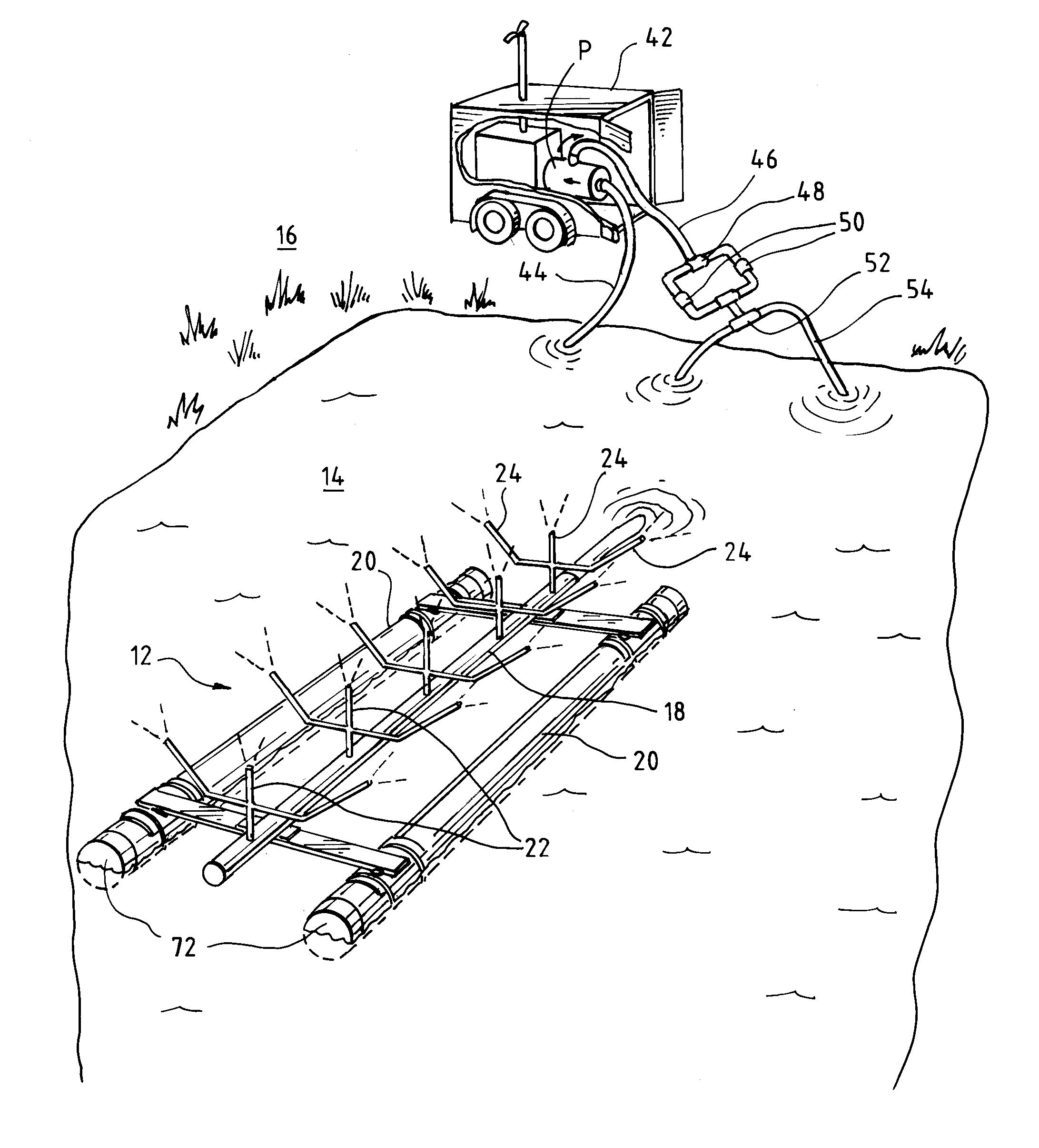
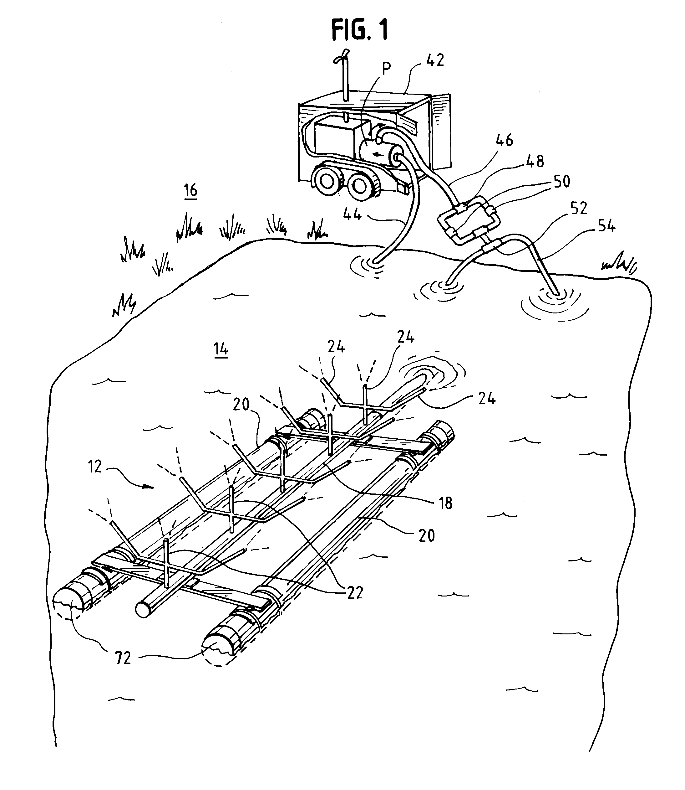
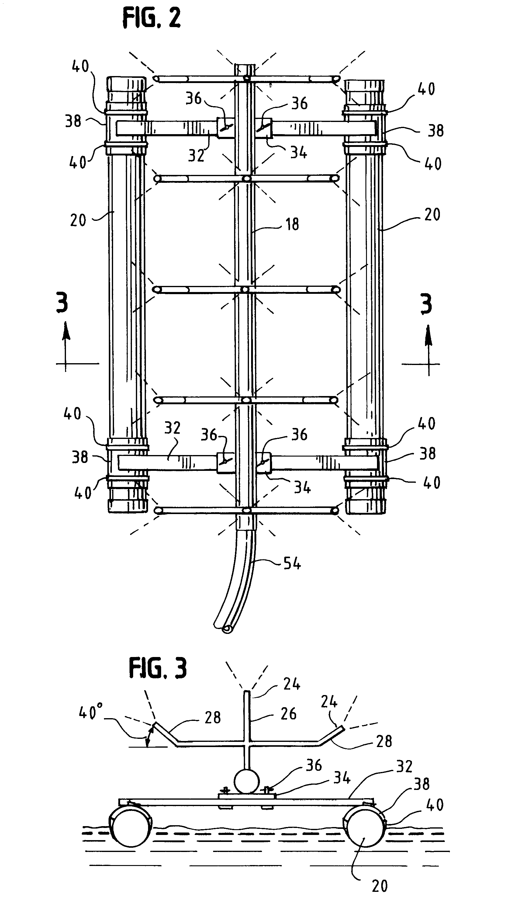
[0023]Turning to the drawings, there is shown in FIGS. 1 one embodiment of the present invention, a floating water evaporation system for use in disposing of excess water from oil and gas drilling operations and from other applications. The system comprises one or more nozzle arrays 12 that float on the surface of a wastewater pond 14 a distance away from the pond periphery or shoreline 16. Each nozzle array 12 comprises a water reservoir 18, two or more upright “Y” shaped arm structures 22 arranged in linear fashion and connected to and extending above the water reservoir 18, and nozzles 24 mounted on each arm structure 22. The water reservoir 18 is mounted to floating pontoons 20 in order to elevate the nozzles 24 a distance above the surface of the pond 14. Water from the pond 14 is pumped through the nozzles 24, which convert the water flow into a patterned spray of evaporable droplets. The droplets preferably have an average diameter of about 300 microns (500 microns for high d...


PUM

PropertyMeasurementUnit
diameteraaaaaaaaaa
acute angleaaaaaaaaaa
diameteraaaaaaaaaa

Abstract

A floating water evaporation system for use in disposing of excess water from oil and gas drilling operations is provided. One or more nozzle arrays float on the surface of a wastewater pond a distance away from the pond shoreline. Each nozzle array includes a series of upright risers that extend above a water reservoir tank. Spray nozzles are mounted on each riser. The water reservoir tank is mounted between floating pontoons that elevate the nozzles a distance above the surface of the pond. Water from the pond is pumped through the nozzles to create a patterned spray of small evaporable droplets.

Description

BACKGROUND[0001]1. Field of the Invention[0002]This invention relates to a system and method for evaporating fluids. More particularly, this invention relates to a system for evaporating wastewater left over from oil or gas drilling, fracturing, and production operations by spraying the water through nozzles located above the surface of a pond away from the pond banks.[0003]2. Description of the Related Art[0004]In oil and gas drilling operations drilling fluid is used to remove the drill cuttings from the bore hole and lubricate the drill. The drilling fluid is usually a mixture of clays, chemicals, weighting material and water. The drilling fluid is pumped down the hollow drill string to the bit where it picks up the drill cuttings, then circulated back up the annular space around the drill string to a drilling mud return line. From the return line the fluid passes across a shaker or screen which catches the larger cuttings while the rest of the drilling mud flows down into a mud ...

Claims


Application Information

Patent Timeline
Patent Type & Authority Patents(United States)
IPC IPC(8): B01D1/20B01D29/00C02F1/12E02B15/04
CPCB01D1/16E21B21/063B01D1/20Y10S159/40Y10S239/19
Inventor HASLEM, DAVID JDOFELMIRE, MICHAEL E.HASLEM, DARRIN N.LAWING, MICHAEL T.
Owner EVAPORITE SYST
Learn More