
Energy storage device for high temperature applications

a technology for energy storage and high temperature applications, which is applied in the manufacture of hybrid capacitor current collectors hybrid capacitor electrolytes, etc., can solve the problems of short useful life, inability to provide sufficient electrical energy, and inability to meet the needs of high-temperature applications, so as to improve the adhesion of the intended coating, increase the surface roughness, and enhance the effect of active material coating or loading

Pending Publication Date: 2021-12-02
ENI SPA
View PDF0 Cites 0 Cited by
  • Summary
  • Abstract
  • Description
  • Claims
  • Application Information

AI Technical Summary

Benefits of technology

This patent text has technical effects on improving the performance of carbon-coated metallic current collectors in electrical devices, particularly for high temperature applications. The current collector can be treated to enhance its surface coating and improve adhesion, and the use of an asymmetric construction with different electrode materials can offer a wide operational voltage window and enhance energy density. The electrolyte composition based on non-aqueous materials and inorganic salts in organic electrolytes is innovative, and the use of such materials with carbon-coated metallic current collectors is highly innovative. If a planar configuration is selected, the slurry can be deposited on both sides of the current collector to increase the available surface area and capacitance of the device.

Problems solved by technology

Devices such as “coin” or “button” sized cells have a limited energy value, and a relatively short duration of useful life.
When the chemical reaction runs close to completion, the cell is no longer able to provide sufficient electrical energy and is regarded as depleted.
Therefore, in comparison of these two types of devices it can said that cells at present levels of technology tend to be slow to charge, are capable of holding the electrical charge for a limited shelf-life period and may deliver a predictable level of electrical energy over an anticipated timescale.
It has been recognised in this field that typical electrochemical energy storage devices are limited by thermally induced degradation of electrolytes and separator when exposed to temperatures exceeding 100° C. Several commercially available devices contain liquid electrolytes (usually organic solvents with low boiling point).

Method used


Image

  • Energy storage device for high temperature applications
  • Energy storage device for high temperature applications
  • Energy storage device for high temperature applications

Examples


Embodiment Construction

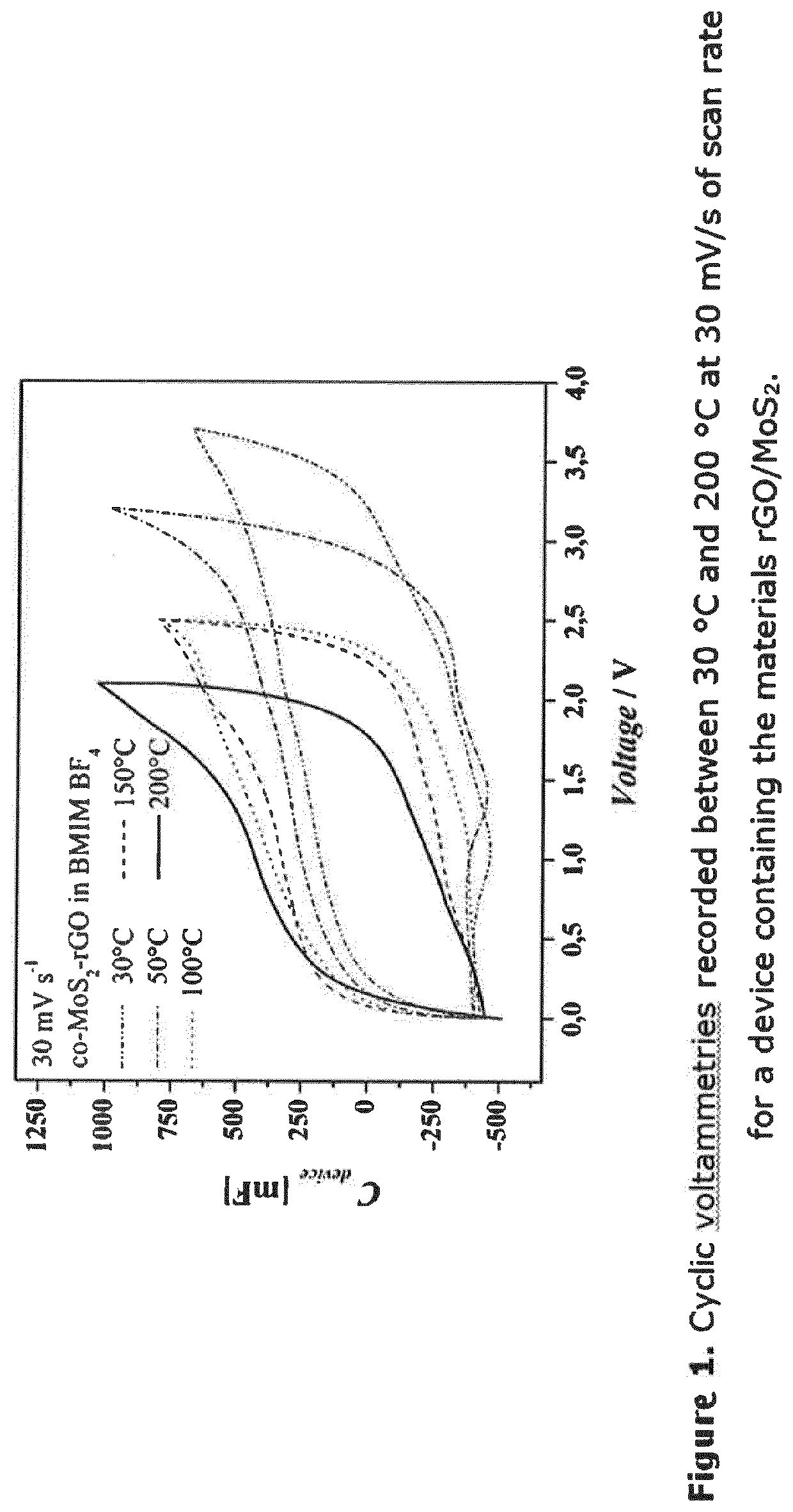
[0058]Referring to the accompanying FIG. 1, a comparison of materials discussed in Shen, Baoshou, et al. Journal of Materials Chemistry A 4.21 (2016): 8316-8327, and Borges, Raquel S., et al. Scientific reports 3 (2013), with an embodiment made in accordance with this disclosure, reveals that the embodiment disclosed here, exhibits capacitance values up to 210 F / g (corresponding to 365 mF / cm2) @ 200° C. with a voltage windows equal to 2.1 V. These values are superior in terms of specific capacitance (both in gravimetric and areal density). The specific capacitance values recorded at the different temperatures are collected in Table 1 below.

TABLE 1Capacitance values recorded at the different temperaturesTemp (° C.)Cs (F / g)Cs (mF / cm2)30174.9306.250202.1353.7100209.3366.1150190.8333.9200208.5364.6

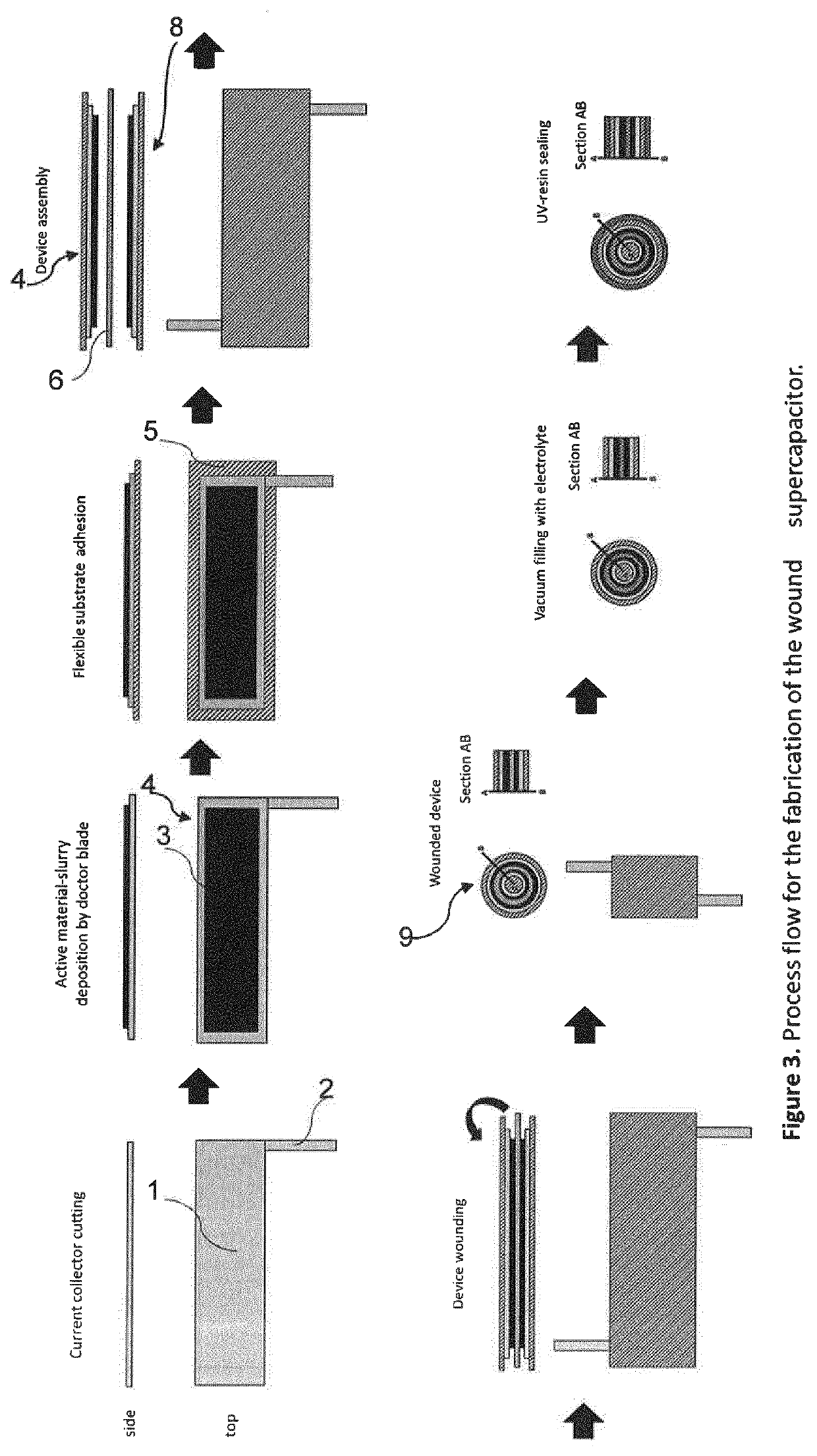
[0059]A device may be assembled according to the following illustrative procedure, representing one possible embodiment of one possible assembly method without limitation, and referring to FIG...


PUM

PropertyMeasurementUnit
temperaturesaaaaaaaaaa
temperatureaaaaaaaaaa

Abstract

An energy storage device, especially a super capacitor, useful for high temperature applications has current collector elements supporting a carbonaceous matrix modified or doped with pseudo-capacitive materials, including one or more transition metal dichalcogenides, transition metal oxides and mixtures thereof, in contact with a non-aqueous electrolyte composition whereby it is possible to exploit the faradic mechanism in addition to the electric double layer mechanism as an energy storage principle.

Description

CROSS REFERENCE TO RELATED APPLICATION[0001]This application claims the benefit under 35 U.S.C. § 119(a) of Italian Application No. 102018000004596 filed on Apr. 17, 2018, and is a national stage application under 35 U.S.C. § 371, of PCT / EP2019 / 059738 filed on Apr. 16, 2019, the contents of both are incorporated by reference herein in their entirety.BACKGROUND OF THE DISCLOSURE1. Field of the Disclosure[0002]This disclosure relates to a device for use in equipment which requires electrical energy, and in particular the disclosed device may be useful as an energy storage device for use in extreme environmental conditions. An electrolyte composition useful in such a device is also disclosed.2. Description of the Related Art[0003]The need for compact energy storage is evident in many fields of technology. Since many pieces of equipment are now required to be capable of operation independently of a power grid, considerable efforts have been made in research into electrical charge storag...

Claims


Application Information

Patent Timeline
Patent Type & Authority Applications(United States)
IPC IPC(8): H01G11/28H01G11/24H01G11/36H01G11/46H01G11/60
CPCH01G11/28H01G11/24H01G11/38H01G11/46H01G11/60H01G11/36H01G11/32H01G11/70H01G11/56H01G11/62H01G11/86Y02E60/13Y02E60/10
Inventor LAMBERTI, ANDREAZAMPATO, MASSIMOCARMINATI, STEFANOSERRAPEDE, MARAGIGOT, ARNAUD NICHOLAS
Owner ENI SPA
Learn More