Method and apparatus for determining the azimuthal orientation of a medical instrument from MR signals

a technology of magnetic resonance imaging and azimuthal orientation, which is applied in the direction of instruments, applications, diagnostic recording/measuring, etc., can solve the problems of not being able to assess or determine the azimuthal orientation of the catheter tip in real time with this known method, and not being able to discern the orientation of the catheter tip orientation, etc., to achieve the effect of detecting the azimuthal orientation only with difficulty

Inactive Publication Date: 2009-10-20
SIEMENS HEALTHCARE GMBH
View PDF34 Cites 10 Cited by
  • Summary
  • Abstract
  • Description
  • Claims
  • Application Information

AI Technical Summary

Benefits of technology

[0009]An object of the present invention is to provide a medical apparatus and an operating method therefor that allow the azimuthal orientation of a medical instrument to be determined by means of magnetic resonance measurements.
[0010]This object is achieved by a medical apparatus with a medical instrument having an acquisition unit for acquiring a magnetic resonance signal that is firmly connected to the medical instrument and exhibits a non-constant (non-uniform) reception sensitivity profile in the azimuthal direction relative to an axis of the medical instrument. Furthermore, the medical apparatus has an evaluation unit that is connected with the acquisition unit and that determines the azimuthal orientation of the medical instrument from the magnetic resonance signal acquired by the acquisition unit. The azimuthal orientation of the instrument can always be determined from the measured magnetic resonance signals due to the non-constant sensitivity profile of the acquisition unit in the azimuthal direction and the fixed connection with the medical instrument. In the ideal case, the sensitivity profile is asymmetric, such that the azimuthal orientation of the tip can be unambiguously determined. Sensitivity profiles in which an ambiguity occurs, for example modulo 180°, can also be used. Even with this limitation, an efficient manipulation of the medical apparatus is possible since, in comparison to previous techniques, only two possibilities are available for selection and the correct orientation can quickly be found by testing. The information thus acquired about the azimuthal orientation of the medical instrument can be superimposed into an overview image of the surrounding anatomy of the patient in the planning (image preparation) for magnetic resonance measurements. Thus, for example, the vessels can be shown in the magnetic resonance image and, as is known, the position of the inserted medical instrument can be displayed. The azimuthal orientation of the medical apparatus can additionally be superimposed, so manipulation of the instrument is made easier for the physician. The use of magnetic resonance measurements for determination of the azimuthal orientation moreover has the advantage that the patient is exposed to no radiation load as occurs, for example, in radiography.
[0012]In a preferred embodiment, the medical instrument has a reference unit for acquisition of the magnetic resonance signal, the reference unit being connected with the evaluation unit. The sensitivity profile of the reference unit differs from the sensitivity profile of the acquisition unit in the azimuthal direction, at least in a limited range. An evaluation of the magnetic resonance measurement implemented with the acquisition unit is made easier by the reference measurement.

Problems solved by technology

It is generally not possible to discern the orientation of the catheter at the insertion point in the body from the orientation of the catheter tip, since the catheter is not resistant to buckling or bending over its entire length.
For this reason, the catheter manipulation and probing place high demands on the experience of the treating physician and often require long radiography times, which is disadvantageous for the patient due to the x-ray dose associated therewith.
It has not been possible, however, to also assess or to determine the azimuthal orientation of the catheter tip in real time with this known method.
The actual curvature, and therewith the azimuthal orientation, however, can be detected only with difficulty even in high-resolution magnetic resonance images.
A continuous representation of the azimuthal orientation of the tip during the entire procedure time thus has not been possible with magnetic resonance measurements.

Method used


Image

  • Method and apparatus for determining the azimuthal orientation of a medical instrument from MR signals
  • Method and apparatus for determining the azimuthal orientation of a medical instrument from MR signals
  • Method and apparatus for determining the azimuthal orientation of a medical instrument from MR signals

Examples


Embodiment Construction

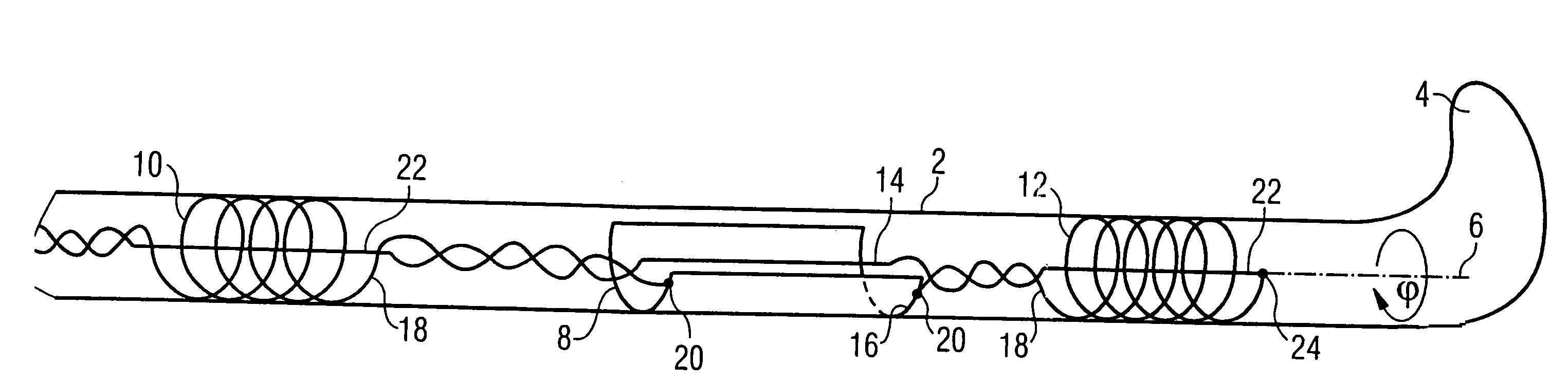
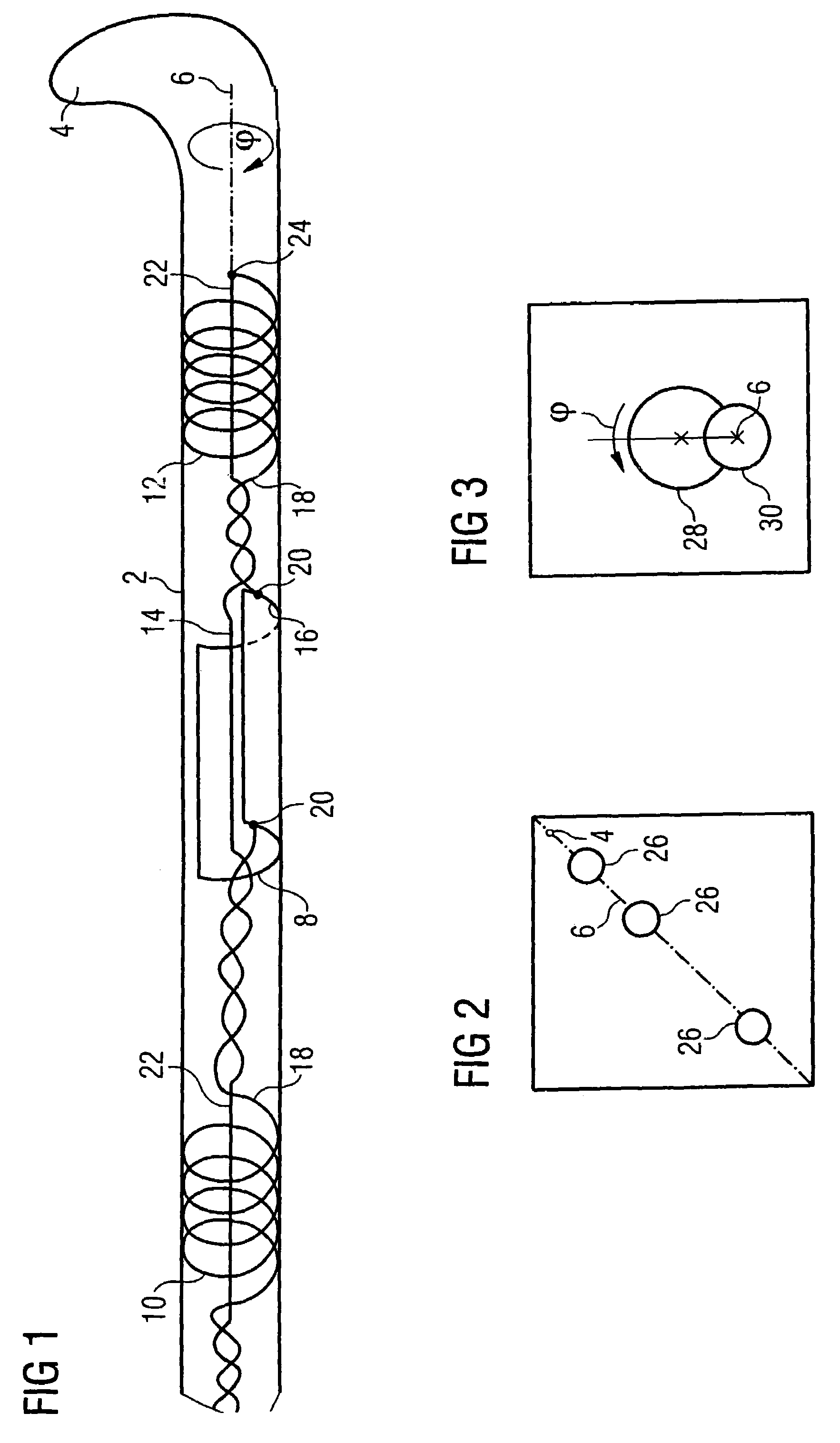
[0022]FIG. 1 shows a section of a catheter 2 with a curved tip 4. The azimuthal orientation of a tip 4 is designated by the angle φ, which is defined relative to the catheter axis 6. The catheter 2 has an acquisition unit, which in this embodiment is a half-open coaxial cable 8, and a reference unit formed by two coils 10 and 12. The axes of symmetry of the coils 10 and 12 and of the coaxial cable 8 coincide with the catheter axis 6. The catheter 2 is resistant to buckling over its entire length, i.e. the coaxial cable 8, both coils 10 and 12 and the tip 4 are in a fixed alignment relative to one another in the azimuthal direction. The coaxial cable 8 is connected in series with the coils 10 and 12, with the coaxial cable 8 between the coils 10 and 12. The distance of the coaxial cable 8 from the coil 10 is thereby larger than the distance to the coil 12. An asymmetry is thereby created in the arrangement from which the orientation of the catheter axis 6 can be determined, as explai...


PUM


Abstract

A medical apparatus, includes a medical instrument with an acquisition unit for a magnetic resonance signal, the acquisition unit exhibiting a non-constant sensitivity profile in the azimuthal direction relative to an axis of the medical instrument. An azimuthal orientation of the medical apparatus is determined by an evaluation unit from magnetic resonance signals received by the acquisition unit.

Description

BACKGROUND OF THE INVENTION[0001]1. Field of the Invention[0002]The present invention concerns a method and apparatus for use with a magnetic resonance imaging apparatus, for determining the azimuthal orientation of a medical instrument from magnetic resonance (MR) signals.[0003]2. Description of the Prior Art[0004]For medical procedures involving in vivo insertion of a medical instrument, for example a catheter, monitoring of the position and alignment of the instrument is frequently necessary. To make placement of the catheter tip easier, the tip generally is formed with a bend. The catheter can thereby also be inserted into branched vessels. Whether the catheter reaches into a branch or passes by the branch depends on the rotation angle of the catheter around its own axis. This rotation angle in the following is designated as the azimuthal orientation. It is desirable to be able to determine the azimuthal orientation of the curved catheter tip during the procedure in order to mak...

Claims


Application Information

Patent Timeline
Patent Type & Authority Patents(United States)
IPC IPC(8): A61B5/05
CPCA61B5/055A61B5/06A61B5/061G01R33/287A61B19/5244A61B19/201A61B2019/5236A61B2019/5251A61B19/52A61B90/36A61B34/20A61B90/11A61B2090/374A61B2034/2051
Inventor SPEIER, PETERWACKER, FRANK
Owner SIEMENS HEALTHCARE GMBH
Why Eureka
Try Eureka