
Disk array apparatus and method for controlling the same

a technology of disk array and disk array, which is applied in the direction of error detection/correction, instruments, computing, etc., can solve the problems of faulty disk drive locking out, disk drive not being able to be recovered by retry processing, and often affecting the reliability of so as to reduce the fault rate of the disk drive and enhance the reliability of the data stored in the disk driv

Inactive Publication Date: 2009-10-20
HITACHI LTD
View PDF22 Cites 8 Cited by
  • Summary
  • Abstract
  • Description
  • Claims
  • Application Information

AI Technical Summary

Benefits of technology

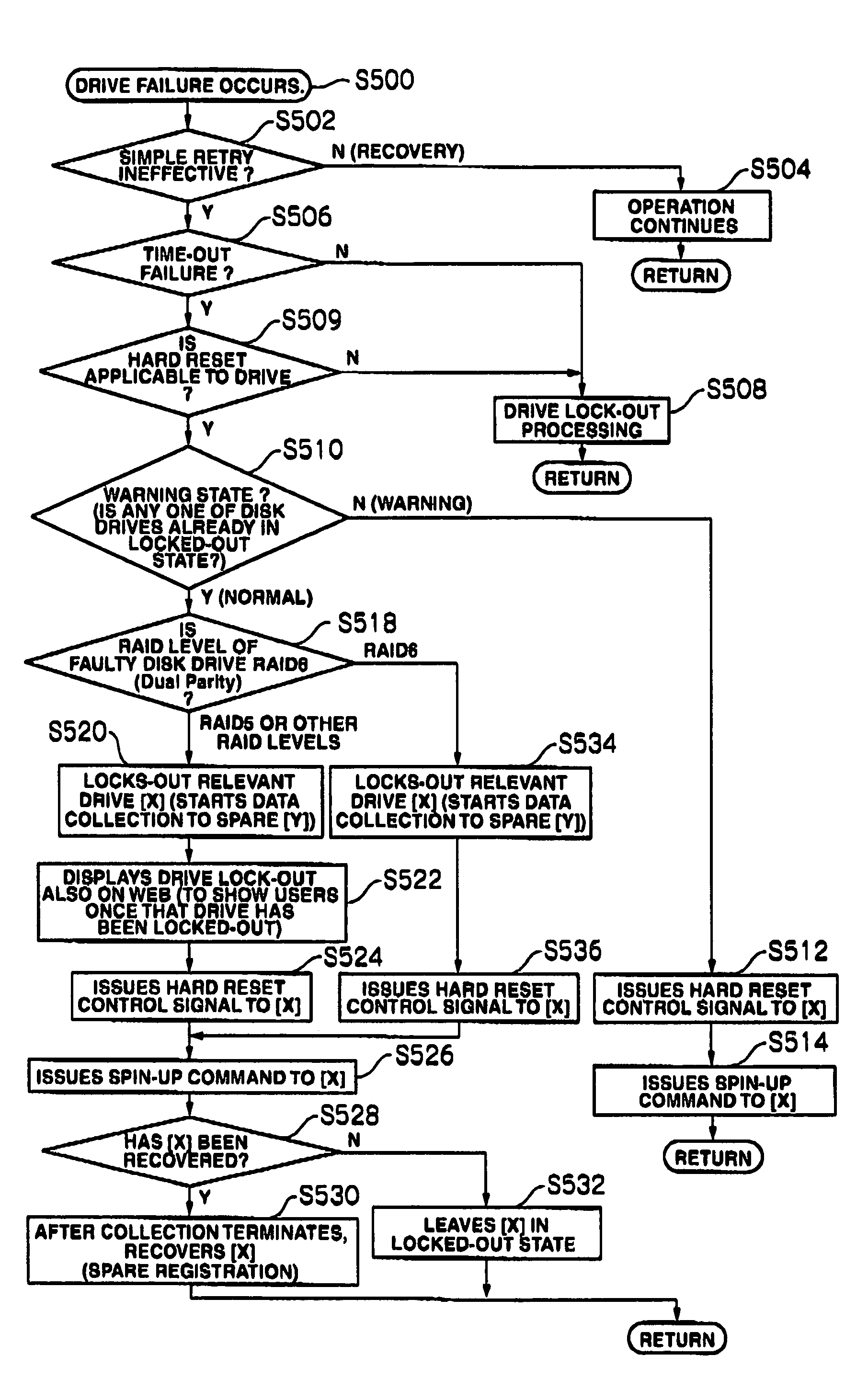
The present invention is a disk array apparatus and a method for controlling it that can reduce the fault rate of disk drives and enhance the reliability of data stored in the disk drives. It provides a technique to restore disk drives in which a time-out trouble or failure has occurred. This is achieved by performing hard resetting on the faulty disk drive, instead of replacing it with another disk drive, which saves resources and reduces workload. The invention also includes a control unit that can specify the failure of a disk drive, issue an instruction to retry a control command, and output a control signal to the faulty disk drive for hard resetting. This allows for effective recovery of data in cases of hard resetting.

Problems solved by technology

For example, in an FC drive that employs Fibre Channel as its interface and whose communication control is complicated, a temporal time-out trouble often occurs.
Although this time-out trouble is a temporal failure of the relevant disk drive hardware or software, the disk drive cannot be recovered by retry processing.
Therefore, when a time-out failure occurs in a disk drive, the faulty disk drive is locked-out and replaced by another disk drive.
Despite the fact that a time-out failure can be normally recovered, the above-described solution not only leads to waste of disk drive resources, but also entails the burden of the work to replace the disk drive.

Method used


Image

  • Disk array apparatus and method for controlling the same
  • Disk array apparatus and method for controlling the same
  • Disk array apparatus and method for controlling the same

Examples


Embodiment Construction

[0026]Embodiments of this invention are described below in detail with reference to the attached drawings. The respective embodiments do not limit the scope of the claims and all characteristics described in the embodiments are not necessarily indispensable as the means for solving the problems of this invention.

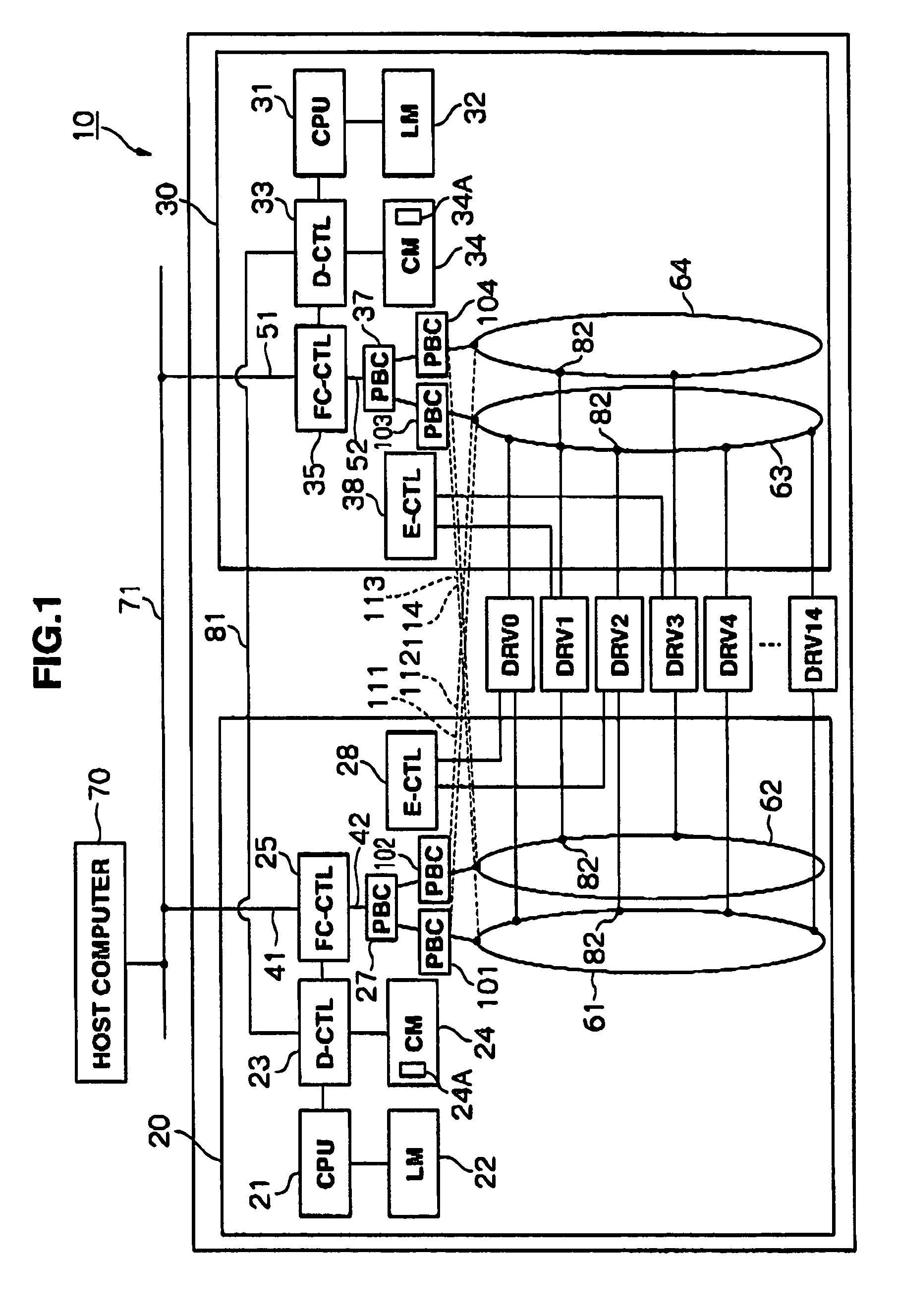
[0027]FIG. 1 shows the configuration of a disk array apparatus 10 according to an embodiment of this invention. The disk array apparatus 10 is connected to a host compute (or host system) 70 via a communication network 71. The host computer 70 is, for example, a server, a personal computer, a workstation, or a mainframe that functions as the host system of the disk array apparatus 10. Examples of the communication network 71 include a LAN (Local Area Network), a SAN (Storage Area Network), the Internet, or private lines.

[0028]In a case of the open-type host computer, data transfer is conducted according to communication protocols such as TCP / IP (Transmission Control Protocol...


PUM


Abstract

A disk array apparatus capable of reducing a disk drive fault rate where a time-out failure has occurred. The disk array apparatus includes a plurality of disk drives, and a control unit for performing data input / output processing of the disk drives in response to a data input / output request from a host system. The control unit includes: a memory for storing control information for specifying a failure of at least one of the disk drives, and failure information of the faulty disk drive, a circuit for specifying, from the failure information, the disk drive in which a time-out failure has occurred, and issuing an instruction to retry a control command to the disk drive, and a circuit for outputting a control signal to the faulty disk drive in order to hard reset the disk drive if the disk drive does not recover from the failure.

Description

CROSS-REFERENCE TO RELATED APPLICATION[0001]This application relates to and claims priority from Japanese Patent Application No. 2005-166227, filed on Jun. 6, 2005, the entire disclosure of which is incorporated herein by reference.BACKGROUND OF THE INVENTION[0002]The present invention relates to a disk array apparatus and a method for controlling the disk array apparatus. More particularly, this invention relates to an improvement of a function to restore a disk drive from a failure.[0003]Recently, in line with the advances in IT technology, attempts have been made to achieve high performance, high capacity, and low cost in a disk array apparatus as a storage controller. The disk array apparatus includes a large number of disk drives allocated in an array. The logical configuration of the disk drives allocated in an array is based on RAID (Redundant Arrays of Independent [or Inexpensive] Disks). A host computer issues a write-access command or a read-access command to the disk arra...

Claims


Application Information

Patent Timeline
Patent Type & Authority Patents(United States)
IPC IPC(8): G06F11/00
CPCG06F11/0727G06F11/1435G06F11/0793
Inventor KANO, AZUMAJIANG, XIAOMING
Owner HITACHI LTD
Learn More