Method of using an electrolysis apparatus with a pulsed, dual voltage, multi-composition electrode assembly

a technology of electrolysis apparatus and electrode assembly, applied in the field of electrolysis system, can solve the problems of limited regional availability, dire consequences for the world's economy, and the vulnerability of the world's energy supply to disruption, and achieve the effect of high hydrogen output flow ra

Inactive Publication Date: 2009-11-03
KUZO HLDG
View PDF18 Cites 21 Cited by
  • Summary
  • Abstract
  • Description
  • Claims
  • Application Information

AI Technical Summary

Problems solved by technology

Unfortunately in a world of rapidly increasing energy needs, dependence on any energy source of finite size and limited regional availability has dire consequences for the world's economy.
In particular, as a country's need for energy increases, so does its vulnerability to disruption in the supply of that energy source.
Additionally, as fossil fuels are the largest single source of carbon dioxide emissions, a greenhouse gas, continued reliance on such fuels can be expected to lead to continued global warming.
Although this process is well developed, due to its reliance on fossil fuels and the release of carbon dioxide during production, it does not alleviate the need for fossil fuels nor does it lower the environmental impact of its use over that of traditional fossil fuels.
Although lowering the electrical consumption of the process is desirable, this process has proven difficult to implement due to the tendency of the hydrogen and oxygen to recombine at the technique's high operating temperatures.
Although a variety of improvements have been devised to improve upon the efficiency of the electrolytic hydrogen production system, to date none of them have been able to make the process efficient enough to make hydrogen-based fuel a viable alternative to fossil fuels.

Method used


Image

  • Method of using an electrolysis apparatus with a pulsed, dual voltage, multi-composition electrode assembly
  • Method of using an electrolysis apparatus with a pulsed, dual voltage, multi-composition electrode assembly
  • Method of using an electrolysis apparatus with a pulsed, dual voltage, multi-composition electrode assembly

Examples


Embodiment Construction

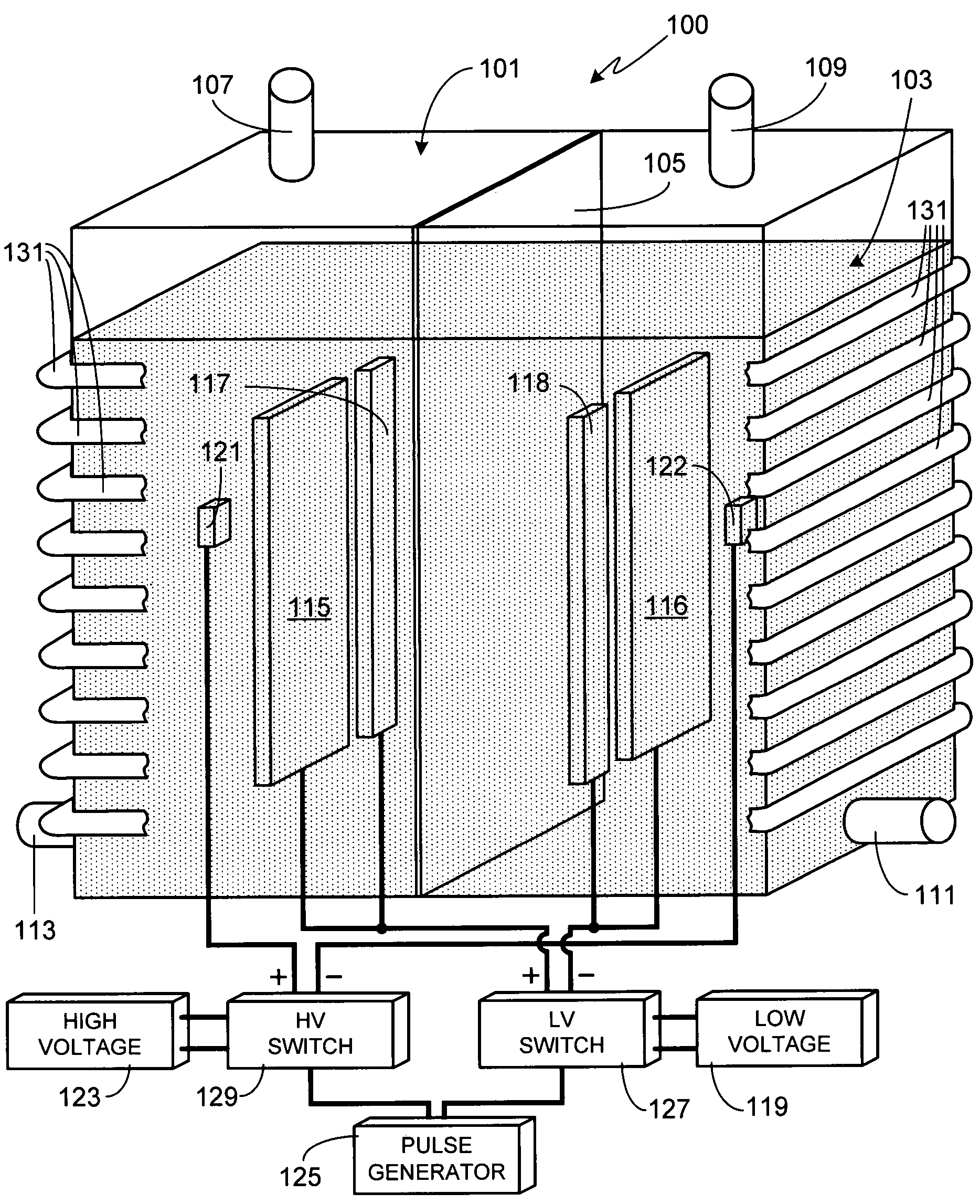
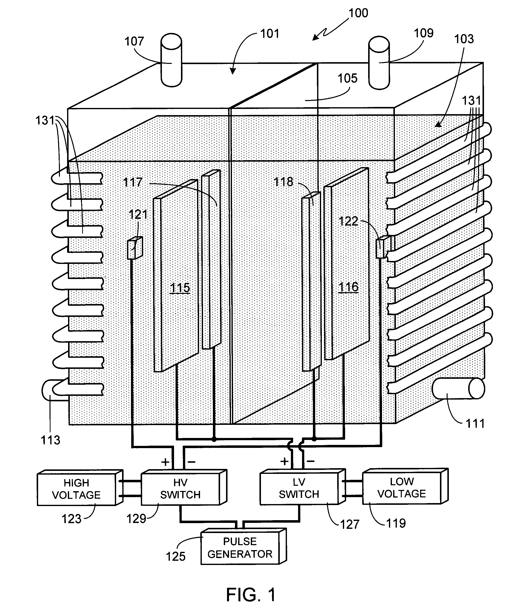
[0027]FIG. 1 is an illustration of an exemplary, and preferred, embodiment of the invention which is used to produce large quantities of hydrogen. Electrolysis system 100 includes a tank 101 comprised of a non-conductive material, the size of the tank depending primarily upon the desired output level for the system, for example the desired quantity / flow rate of hydrogen to be generated. Although tank 101 is shown as having a rectangular shape, it will be appreciated that the invention is not so limited and that tank 101 can utilize other shapes, for example cylindrical, square, irregularly-shaped, etc. Tank 101 is substantially filled with water 103. Within water 103 is an electrolyte, the electrolyte necessary to achieve the desired level of conductivity within the water. A preferred electrolyte is potassium hydroxide, although the invention is not limited to this specific electrolyte. For example, sodium hydroxide can also be used. Although a typical electrolysis system used to de...


PUM

PropertyMeasurementUnit
voltageaaaaaaaaaa
voltageaaaaaaaaaa
voltageaaaaaaaaaa

Abstract

A method of operating an electrolysis system (100) to achieve high hydrogen output flow rates is provided. At least three types of electrodes are positioned within an electrolysis tank (101), the three types including at least one pair of low voltage electrodes (115 / 117) comprised of a first material, at least one pair of low voltage electrodes (117 / 118) comprised of a second material different from the first material, and at least one pair of high voltage electrodes (121 / 122). The low voltage and high voltage cathode electrodes are positioned within one region of the tank (101) while the low voltage and high voltage anode electrodes are positioned within the second region of the tank (101), the two regions separated by a membrane (105). The tank (101) is filled with an electrolyte containing water (103). The power supplied to the low and high voltage electrodes is simultaneously pulsed.

Description

CROSS-REFERENCES TO RELATED APPLICATIONS[0001]This application is a continuation-in-part of U.S. patent application Ser. No. 11 / 480,590, filed Jul. 3, 2006, now abandoned which is a continuation of U.S. patent application Ser. No. 11 / 450,042, filed Jun. 9, 2006 now abandoned.FIELD OF THE INVENTION[0002]The present invention relates generally to electrolysis systems and, more particularly, to a method of operating a high efficiency electrolysis system.BACKGROUND OF THE INVENTION[0003]Fossil fuels, in particular oil, coal and natural gas, represent the primary sources of energy in today's world. Unfortunately in a world of rapidly increasing energy needs, dependence on any energy source of finite size and limited regional availability has dire consequences for the world's economy. In particular, as a country's need for energy increases, so does its vulnerability to disruption in the supply of that energy source. Additionally, as fossil fuels are the largest single source of carbon dio...

Claims


Application Information

Patent Timeline
Patent Type & Authority Patents(United States)
IPC IPC(8): C25B1/04C25B9/17C25B9/19
CPCC25B1/04C25B15/00C25B9/06Y02E60/366Y02E60/36C25B9/17
Inventor DAVIDSON, NEHEMIA
Owner KUZO HLDG
Why Eureka
Try Eureka