
Method and system for concurrent localization and display of a surgical catheter and local electrophysiological potential curves

a technology of electrophysiological potential and surgical catheter, which is applied in the field of concurrent localization and display of surgical catheters and local electrophysiological potential curves, can solve the problems of only using special and expensive catheters, long examination times, and complex complete systems, and achieves the effect of facilitating or even simply enabling data to be assigned to one another

Inactive Publication Date: 2009-11-03
SIEMENS HEALTHCARE GMBH
View PDF17 Cites 16 Cited by
  • Summary
  • Abstract
  • Description
  • Claims
  • Application Information

AI Technical Summary

Benefits of technology

The invention is a method to help electrophysiologists accurately position an ablation catheter in the heart. It uses an x-ray fluoroscopy system and a reference catheter to record electrophysiological potential curves in different positions. The data from these curves is then assigned to markers on the x-ray image, which can be easily identified on the screen. This allows the user to easily find the ideal site for ablation. The invention also provides a cost-effective and reliable way to assist the user with the precise local positioning of the operation catheter.

Problems solved by technology

The problem for electrophysiologists who record the electrophysiological potential curves is therefore to deliver the catheter to an area where it has already previously been and for which the electrophysiological potentials have been recorded.
On the basis of the potential curves, he has hitherto been able to orientate himself in the space, which however can lead to long examination times.
The complete system is very complex and expensive.
He can only use special and expensive catheters.

Method used


Image

  • Method and system for concurrent localization and display of a surgical catheter and local electrophysiological potential curves
  • Method and system for concurrent localization and display of a surgical catheter and local electrophysiological potential curves

Examples


Embodiment Construction

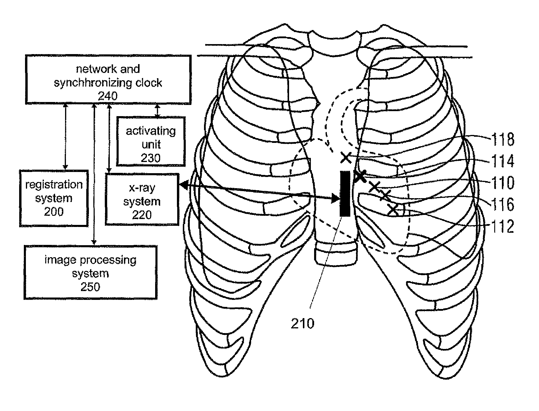
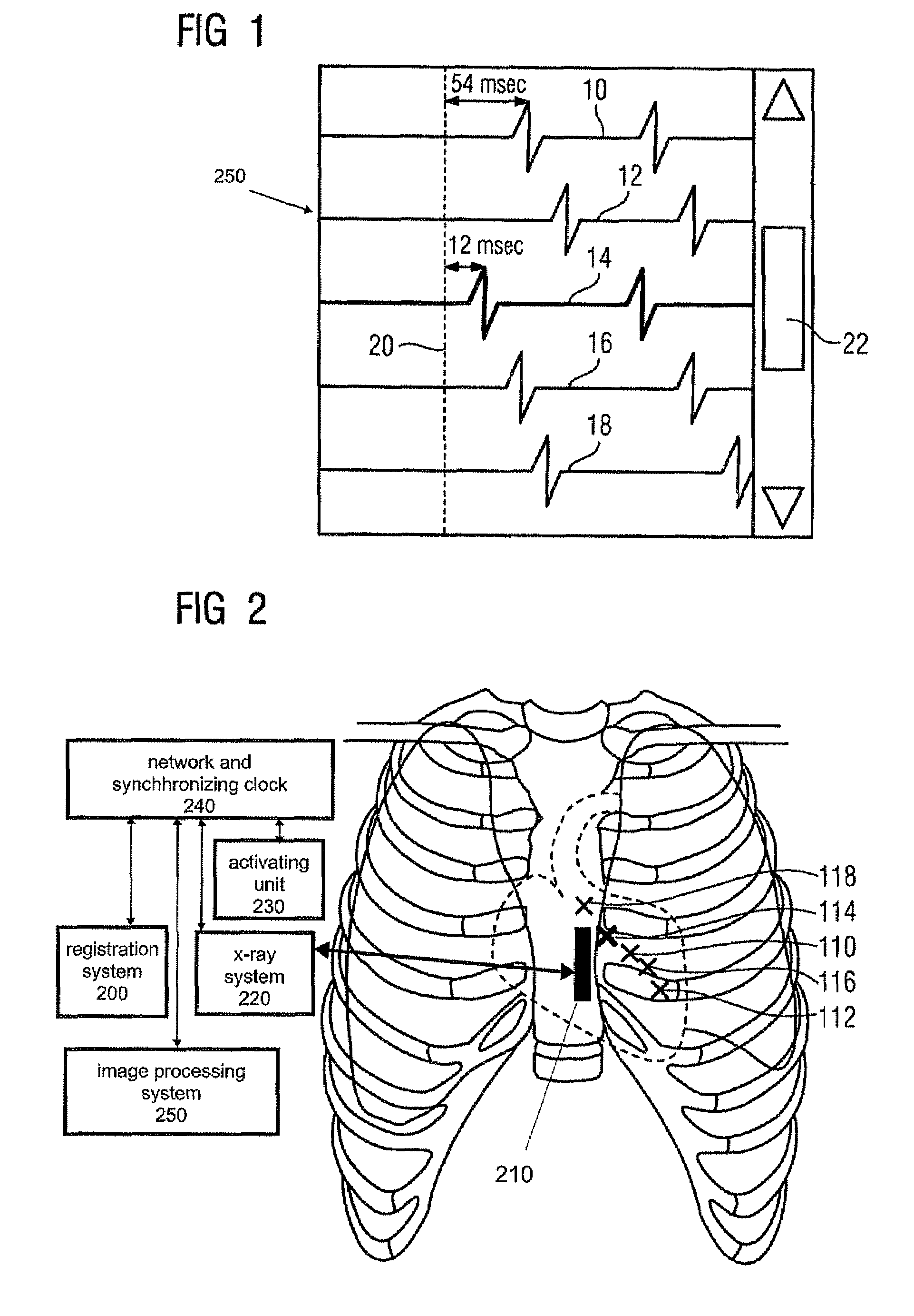
[0024]FIG. 1 shows the screen 250 of an electrophysiological registration system 200 with five measuring curves 10, 12, 14, 16 and 18, which are recorded by an ablation catheter 210. Since an abnormal change in the heart appears in each heartbeat cycle, the curves 10, 12, 14, 16 and 18 have essentially the same form. The only differ in terms of their temporal insertion, the curves being in fact displayed in relation to a reference time, which is measured by the reference catheter and is indicated here by a dashed line 20. The dashed line corresponds with a reference pulse signal which the reference catheter receives and the ablation catheter receives this signal in a temporally displaced manner. By way of example, the delay time for the curve 10 and the curve 14 is shown. In the curve 10, the pulse which forms the main signal has a delay time of 54 msec compared with the reference catheter. For instance, the curve 10 was recorded here as the ablation catheter was located in an area ...


PUM


Abstract

A method for providing measuring data for the precise local positioning of an ablation catheter comprises the recording of electrophysiological potential curves in a plurality of positions of the ablation catheter with regard to a potential measurement on a reference catheter. An x-ray image is recorded in each of the positions and the position of the ablation catheter in each instance on the x-ray image is characterized by a marker. The electrophysiological potential curves are coupled in a data-related manner with the markers. When a marker on the screen displaying the x-ray image is clicked on, the associated electrophysiological potential curves appear highlighted on another screen, if necessary in color or with increased brightness. Conversely, the x-ray image with the marker is queried, i.e. displayed and the marker highlighted when the potential curve is activated on a screen displaying the potential curve.

Description

CROSS REFERENCE TO RELATED APPLICATIONS[0001]This application claims priority to the German Application No. 10 2005 014 854.9, filed Mar. 30, 2005 which is incorporated by reference herein in its entirety.FIELD OF INVENTION[0002]The invention relates to a method for providing measuring data for the precise local positioning of an operation catheter, in particular an ablation catheter.BACKGROUND OF INVENTION[0003]An ablation catheter used with the operation concerning the heart serves to ablate tissue from the interior wall of the heart with the purpose of ablating (isolating) atrioventricular channels on the interior wall of the heart. The aim here is to remedy a medical condition relating to the functionality of the heart. This includes cardiac arrhythmias. One problem with different arrhythmias, for example with the AV Nodal Reentry Tachycardia, is that the abnormal area of the heart must be located, i.e. the best area for an ablation must be determined.SUMMARY OF INVENTION[0004]T...

Claims


Application Information

Patent Timeline
Patent Type & Authority Patents(United States)
IPC IPC(8): A61B5/04
CPCA61B5/042A61B5/7445A61B5/06A61B2018/00351A61B6/12A61B18/1492A61B5/065A61B5/283
Inventor RAHN, NORBERTWESTPHAL, ARNE
Owner SIEMENS HEALTHCARE GMBH
Learn More